


2-9
IPL T S Series • Installation and Operation
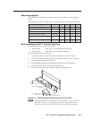
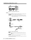
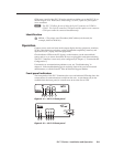
COM ports 1 and 2 of the IPL T S2 can be wired in a similar way as the IPL T S6, as
shown in figure 2-10. Both can be wired using a 3.5 mm, 5-pole or 3-pole captive
screw connector.
N
The IPL T S2 allows for use of either the 9-pin D connector on COM1 or
COM2. The 9-pin D connector COM ports and the captive screw connector
COM ports cannot be connected simultaneously.
Identification
j
UID # — The unique user ID number (MAC address) of the unit (for
example, 00-05-A6-00-00-01).
Operation
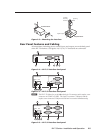
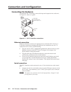
Connect power cords and turn on the output display devices (projectors, monitors,
VCRs), control devices (switchers, scalers, distribution amplifiers), interface, and
input devices (PC, laptop, network equipment).
Check indicator LEDs on the PC/laptop, on the interface, on the network hub/
router, and so on, to ensure that all the devices are plugged in and communicating.
The IPL T S interface is now ready to be configured (see chapter 3, “Connection and
Configuration”).
If connection or communication problems occur, see “Troubleshooting” in
chapter 4. If the troubleshooting tips do not help, check with your local network
administrator, or call the Extron S
3
Sales & Technical Support Hotline.
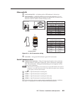
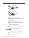
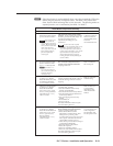
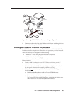
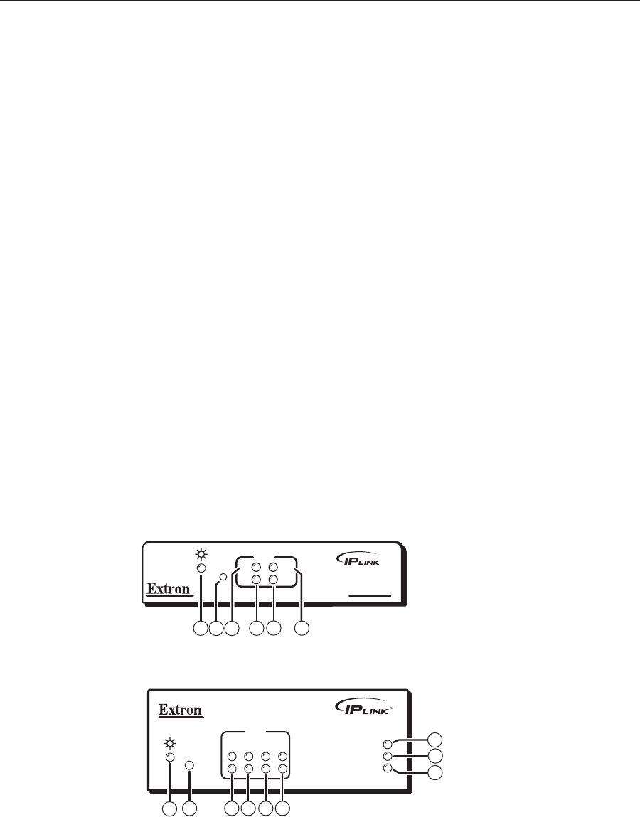
Front panel indicators
The front panels of the IPL T S interfaces have several indicator LEDs that show the
current status of communications to and from the unit. A reset button (b) is also
available from the front panel, in a small recess next to the Power LED.
IPL T S1
COM
TX
RX
RTS
CTS
R
1
4
6
3
5
2
Figure 2-11 — IPL T S1 front panel
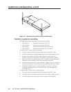
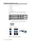
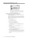
IPL T S2
1
R
100
COM
TX
LINK
ACT
2
RX
RTS
CTS
1
3
2
4 5 6
9
7
8
Figure 2-12 — IPL T S2 front panel