


QS-1
IPL T S Series • Quick Start
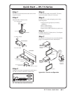
Step 1
Turn power off and disconnect the device from
its power source.
Step 2
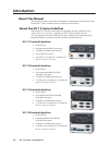
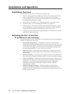
Mount the IPL T S Series unit:
• on a projector
Projector Mount
IPL T S2
1
R
100
COM
TX
RX
RTS
CTS
LINK
ACT
2
2
4
Digital Projector
Mounting
Bolt
Projector
Mounting
Bracket
• under a desk
IPL T S2
1
R
100
COM
TX
LINK
ACT
2
RX
RTS
CTS
Furniture Mount
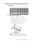
• or on a rack
Rack Mount
(2) 4-40 x 3/16" Screws
Use 2 mounting holes on
opposite corners.
1U Rack Shelf
1/4 Rack Width False Front
Face Plate
IP
L T
S
2
1
R
100
COM
TX
LINK
ACT
2
RX
RTS
CTS
IP
L
T
S
2
1
R
100
COM
TX
LINK
ACT
2
RX
RTS
CTS
IP
L
T
S
2
1
R
100
COM
TX
LINK
ACT
2
RX
RTS
CTS
®
®
®
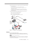
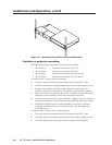
Step 3
Connect a local area network (LAN) cable from a
PC, hub, or router to the IPL T S Series unit.
COM
1
LAN
00-05-A6-00-30-06
POWER
12V
.5A MAX
COM5
TX RX TX RX
COM6
COM3
TX RX TX RX
COM4
COM2
IPL T S6 Ethernet Control Interface
Step 4
Connect RS-232 cables from the IPL T S Series
unit to the audio/video (A/V) devices.
Step 5
Connect power cords and apply power in the
following order:
• output devices (projectors, monitors,
speakers)
• IPL T S Series device
• PC or serial controller
• input devices (DSS, cable boxes, and so on)
Step 6
Configure the IPL T S Series device. See chapter
3 for more information.
Step 7
Test the IPL T S Series device via its default Web
pages. See chapter 4 for more information.
COM
1
LAN
12V
.5A MAX
COM
1
LAN
12V
.5A
MAX
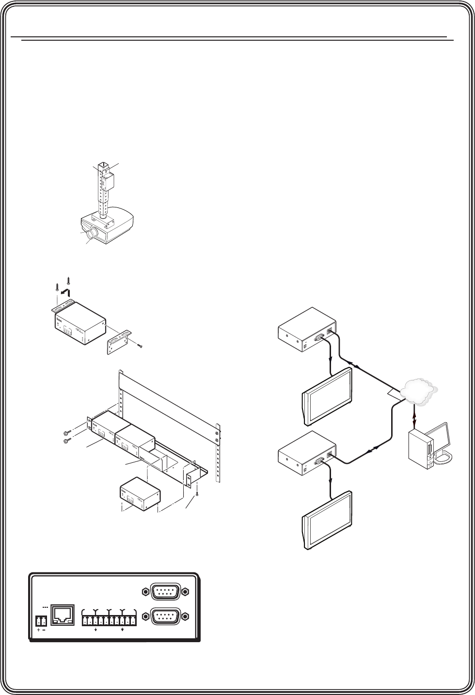
Ethernet
RS-232
Remote User
Control and
Administrator
Monitoring
Extron
IPL T S1
Ethernet Control
Interface
RS-232
Plasma Display
Ethernet
TCP/IP
Network
Extron
IPL T S1
Ethernet Control
Interface
Plasma Display
Typical IPL T S Series configuration
Quick Start — IPL T S Series