


Installation and Operation, cont’d
IPL T S Series • Installation and Operation
2-10
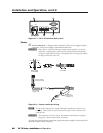
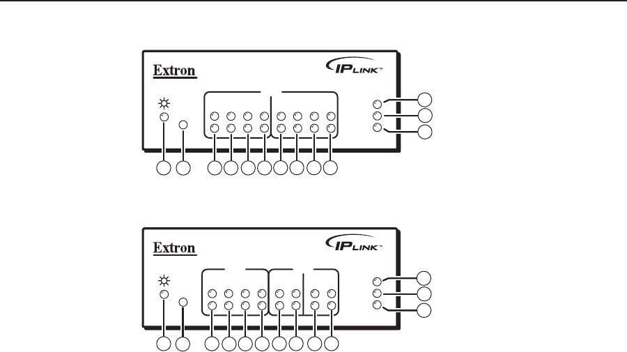
IPL T S4
R
100
LINK
ACT
1
COM
TX
2
RX
RTS
CTS
3
TX
4
RX
RTS
CTS
9
7
8
1
3
2
4 5 6
3
4 5 6
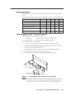
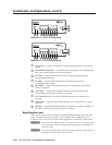
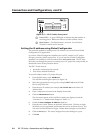
Figure 2-13 — IPL T S4 front panel
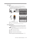
IPL T S6
R
100
LINK
ACT
1
COM
TX
2
RX
RTS
CTS
3
COM
TX
4
5
6
RX
TX
RX
1
3
2
4
5 6
9
7
8
3
4
3
4
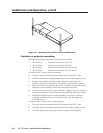
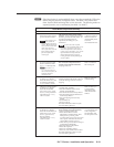
Figure 2-14 — IPL T S6 front panel
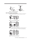
a
Power LED — A green LED lights to indicate that the interface is receiving
power.
b
Reset button (recessed) — A multi-function reset button. See “Resetting the
unit” later in this chapter for more information.
c
TX LEDs — A green LED indicates data is being transmitted from the
corresponding serial port.
d
RX LEDs — A green LED indicates data is being received by the
corresponding serial port.
e
RTS LEDs — A green LED indicates that the corresponding serial port is
ready to send data.
f
CTS LEDs — A green LED indicates that the device controlled by the
corresponding serial port is ready to accept data.
g
ACT (Activity) LED — A yellow LED indicates that data is being sent/
received.
h
LINK LED — A green LED indicates that the unit is connected to an active
network.
i
100 LED — A green LED indicates that the connection speed is 100 Mbps. If
the LED is not lit, the connection speed is 10 Mbps.
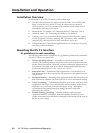
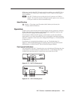
Resetting the unit
There are five reset modes available by pressing the Reset button (
b
) on the side
panel. The Reset button is recessed, so use a pointed stylus, ballpoint pen, or
Extron Tweeker to access it. See the following table for a summary of the modes.
C
Review the reset modes carefully. Using the wrong reset mode may result
in unintended loss of flash memory programming, port reassignment, or a
controller reboot.
C
The reset modes listed below (with the exception of Mode 2) close all open IP
and Telnet connections and close all sockets.