


MLC 52 MediaLink Controllers • Introduction 6
MLC 52 MediaLink Controllers • Installation and Configuration
6
Installation and
Configuration
This section describes the front, side, and rear panel features of the four MLC 52 models,
and provides procedures for installing and configuring the controllers. Topics include:
• Rear Panel and Cable Connections
• Installation Steps
• Replacing the Faceplate (US Models Only)
• Replacing Button Labels
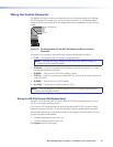
• Wiring the Control Connector
• Configuring the MLC 52 Using IR
• Setting Up an MLC 52 VC Model with an Extron Amplifier
• Mounting the MLC 52
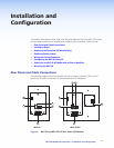
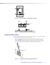
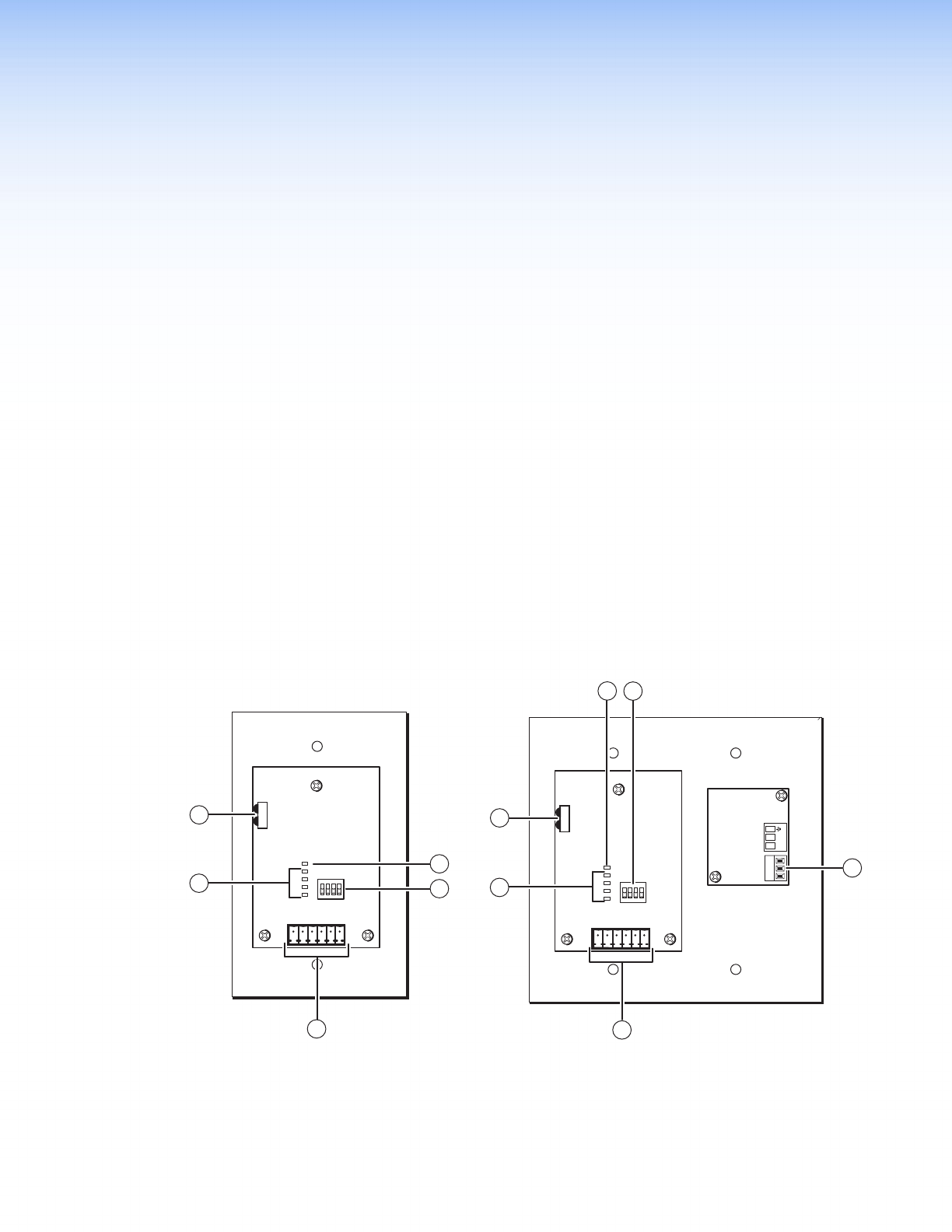
Rear Panel and Cable Connections
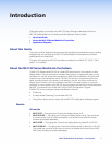
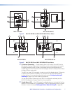
The following diagrams show the locations of the connector, switches, LEDs, and IR
sensors on the back of the MLC 52 with standard and VC faceplates.
Figure 3. MLC 52 and MLC 52 VC Rear Views (US Models)
5
VOL/
MUTE
+ 10V
1
1
2
3
4
E
ON
234
5
2
6
1
1
1
2
3
4
E
ON
2 3 4
Tx
IR OUT
GND
IR IN
GND
+ 12V
3
6
4
Tx
IR OUT
GND
IR IN
GND
+ 12V
3
2
1
5
VOL/
MUTE
+ 10V
1
1
2
3
4
E
ON
234
5
2
6
1
1
1
2
3
4
E
ON
2 3 4
Tx
IR OUT
GND
IR IN
GND
+ 12V
3
6
4
Tx
IR OUT
GND
IR IN
GND
+ 12V
3
2
1
MLC 52 VC
MLC 52