


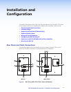
Wiring an IRL 20
The Extron IRL 20 is a hard wired IR signal receiver that can be used with the MLC 52 and
an IR remote control. The IRL 20 receives a signal via its front panel (or an IR sensor) from
the IR remote control, and outputs a modulated IR signal via an IR emitter.
Wire and connect the IRL 20 to the MLC 52 as follows:
1. If it has not been done, cut the required length of Extron CTL (Comm-Link) cable to
connect the MLC 52 to the IRL 20 (see Recommended Cables on page 62 for
cable part numbers).
The maximum total distance between an Extron controller and the IRL 20 is 150 feet
(45.7 m).
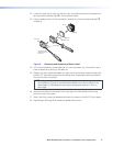
2. Attach a 3.5 mm, 5-pole captive screw connector to the end of the cable that will be
plugged into the IRL 20.
Tx
IR OUT
GND
IR IN
GND
+ 12V
+12V
GND
CM
ModIR
SCP
+12V
GND
CM
ModIR
SCP
IR SNSR
IRL 20
GND
SIG
+5V
D
B
A
+12 V
GND
Modulated IR
C
B
A
+12 VDC
Ground (Gnd)
A
B
External Power Supply
(12 VDC, 1 A max.)
Control Connector
for MLC 52 Series
(Rear Panel)
F E D C B A
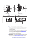
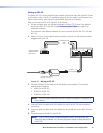
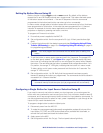
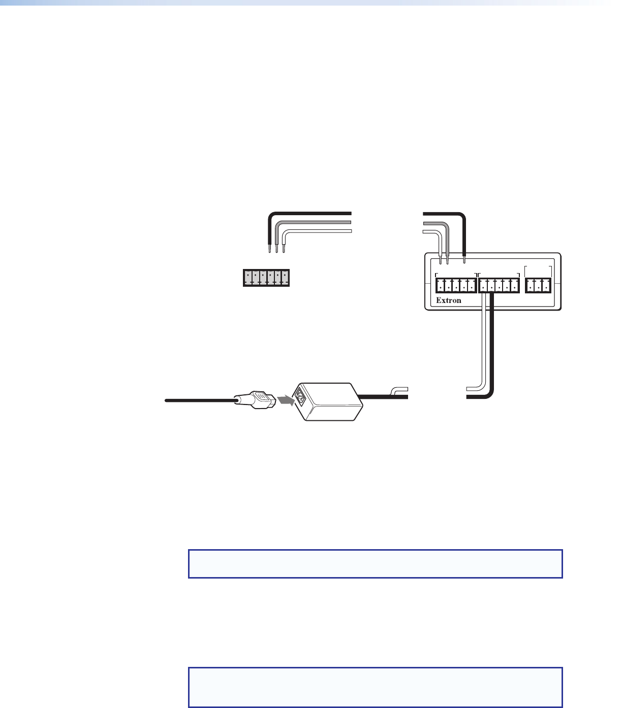
Figure 13. Wiring an IRL 20
3. Connect the wires on the other end of the cable to the provided 3.5 mm 6-pole
captive screw connector.
• A (MLC) to A (IRL 20)
• B (MLC) to B (IRL 20)
• C (MLC) to D (IRL 20)
NOTE: Do not connect more than one IRL 20 (either in parallel or in series) to an
Extron device.
4. Plug the 5-pole connector end of the cable into one of the IRL 20 communications
connectors.
5. Plug the 6-pole connector end of the cable into the control port on the MLC 52 back
panel.
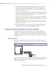
6. Connect power to the MLC or the IRL 20.
NOTE: The +12 VDC power is shared between the MLC 52 and the IRL 20
when they are connected. You can wire the power supply to either the MLC or
the IRL 20.
MLC 52 MediaLink Controllers • Installation and Configuration 14