


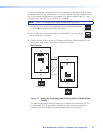
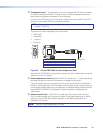
Figure 21_Wiring MLC VC and MPA
COMPUTER
OUT
AUDIO OUT
Projector
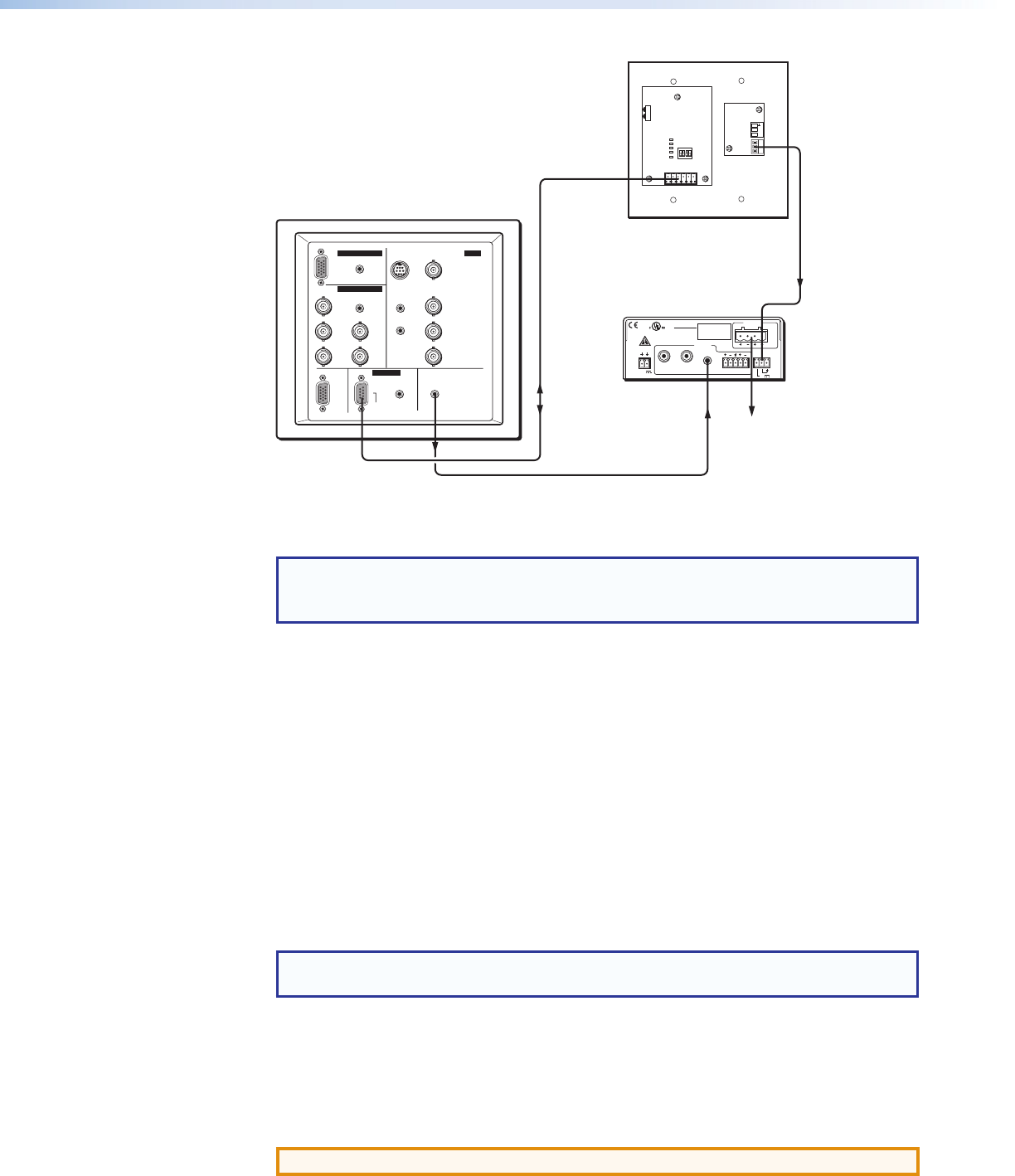
RS-232 or IR
Projector Control
Any input on the MPA
can be used.
To Loudspeakers
MPA 152
MLC 52 VC Series
P
R
/R-Y
P
B
/B-Y
REMOTE
AUDIO
AUDIO AUDIO
Y/C VIDEO
PC
R
R
L Y
G H/Cs
B V
RS-232
COMPUTER IN-2
CONTROL
COMPUTER IN-1 AV IN
Tx
IR OUT
GND
IR IN
GND
+ 12V
VOL/
MUTE
+ 10V
1
1
2
3
4
E
ON
2 3 4
POWER
12V
3A MAX
OUTPUT
4/8
OHMS
CLASS 2 WIRING
DO NOT GROUND
OR SHORT
SPEAKER OUTPUTS!
INPUTS
L
R
L
R
REMOTE
VOL/MUTE
10V 50mA
L
MPA 152
R
C US
LISTED
17TT
AUDIO/VIDEO
APPARATUS
Audio Out
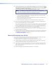
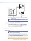
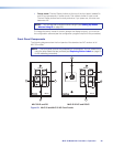
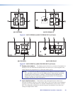
Figure 20. Wiring an MLC 52 VC Controller and an MPA Series Power Amplifier
to a Typical Projector
NOTE: Audio is now controlled from the MPA instead of from the projector. For best
results, ensure that the audio volume of the projector is set to maximum (assuming
that the monitor output for audio is variable).
Configuring the MLC 52 IR VC and MLC 52 RS VC Vol Buttons
By default, the MLC 52 has two buttons on the front panel programmed for volume
control (Vol
>
and Vol
<
). However, on the MLC 52 VC models, these buttons are not
needed for volume control and can be programmed for other uses. To reprogram the Vol
buttons, you can use IR Learning (see Configuring Using IR Learning on page 18) or
the MLC 52 configuration program (see the program help file).
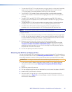
Mounting the MLC 52
After the system has been cabled, configured, and tested, you can mount the MLC.
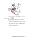
Preparing the Site
NOTE: The installation of the MLC 52 must conform to national and local electrical
codes and to the equipment size requirements.
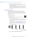
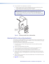
Installation using a UL listed wall box is recommended for most mounting options, but
for US models a mounting bracket can be used instead. To cut a hole in the mounting
surface for the controller, use the dimensions from one of the rough-in templates provided
under Templates for the MLC 52 and MLC 52 VC (US Models) on page 64 as a guide
to measure and mark the hole. The templates provide measurements for installing the
MLC with either an electrical box or a mounting bracket.
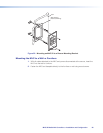
ATTENTION: The templates are not to scale and are provided for reference only.
MLC 52 MediaLink Controllers • Installation and Configuration 23