


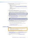
c Configuration switches — When set to On, these DIP switches place the MLC in IR
learning or data transfer mode, or disable IR repeats.
• Switch 1: Enables IR learning.
• Switch 2: Enables data transfer, such as cloning the current MLC configuration
onto another MLC 52 (see Configuring Using IR Data Transfer (IR Beaming)
on page 15).
• Switch 3: Disables IR repeats during playback. For most applications, this switch
is placed in the off position.
Switch 4 is not used.
d Volume control (VC models only) connector — Connect an amplifier such as
the Extron MPA 152 or a PoleVault switcher to this direct-insertion captive screw
connector to enable the volume control knob on the MLC 52 VC front panel to raise
and lower the volume on the display device via the amplifier or switcher.
NOTE: This port must be connected only to an Extron device such as a
PoleVault
®
PVS switcher, an MP Series microphone-to-line preamplifier, or an
MPA Series audio amplifier.
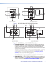
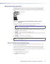
e Display control and power connector — This shared six-pole, 3.5 mm captive
screw connector is used for IR and RS-232 control of the display device and for DC
power (see Wiring the Control Connector on page 12 for information on how to
connect supported devices to the MLC).
NOTE: The RS-232 projector control port is present on this connector but not
functional on the IR models. The port is functional only on the RS models.
f IR Learning indicators — Each button on the MLC front panel has four memory
blocks, which can be programmed with up to four IR (or RS-232) commands. The
IR Learning indicator LEDs provide visual feedback indicating the following:
• Which of the four memory blocks contains a command
• Which of the four memory blocks is ready to be programmed or configured
• The IR learning status of the controller
See Configuring Using IR Learning on page 18 for details.
Installation Steps
ATTENTION:
• Installation and service must be performed by authorized personnel only. UL
listed electrical boxes are recommended.
• If using an electrical box, ensure that it is grounded properly.
To install and set up the MLC:
1. If applicable, prepare the installation site (see Mounting the MLC 52 on page 23 and
Mounting an Electrical Box on page 63; or see the instructions provided with the
optional faceplate, mounting device, or electrical box).
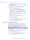
2. Make and install button labels as desired (see Replacing Button Labels on
page 10).
MLC 52 MediaLink Controllers • Installation and Configuration 8