


3. If you want to use a different faceplate from the one that is attached, remove the
installed faceplate from the MLC, and replace it with the new one (see Replacing the
Faceplate [US Models Only]).
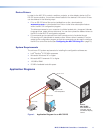
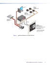
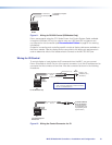
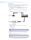
4. Attach cables to the rear of the MLC and to the display device as well as any optional
devices such as the MPA Mini Power Amplifier, IR emitters, and IRL 20.
5. Connect power cords and turn on all the devices, including the MLC.
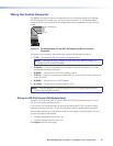
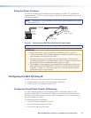
6. Configure the controller using one of the following methods:
• IR learning (see Configuring Using IR Learning on page 18)
• IR data transfer (beaming) (see Configuring Using IR Data Transfer (IR
Beaming) on page 15)
• Configuration program (see Using the MLC 52/DVCM 50 Configuration
Program on page 47 to start the program. See the configuration program help
file for detailed information on using the software.)
7. Test the system: press the MLC buttons, watch the display, and listen to the audio
output to determine whether the output devices are responding correctly (powering
on and off, switching inputs, and so on).
If the outputs are not responding, ensure that all devices are plugged in and receiving
power. Check the cabling, and make adjustments as needed.
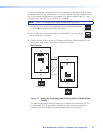
8. Mount the MLC to the wall or furniture.
a. Disconnect the MLC power supply at the power source end (not at the MLC end).
b. Disconnect power from the other devices.
c. Secure the faceplate onto a UL-approved electrical wall box, a mounting bracket,
a wall, or furniture (see Mounting the MLC 52 on page 23).
d. Restore power to the MLC and to the connected devices.
Replacing the Faceplate (US Models Only)
The MLC is delivered with a black plastic faceplate attached, and an additional one-
gang plastic faceplate in white. You can replace the black faceplate with the white one
or with a different one-gang sized faceplate of your own. You can also replace it with
the MLM 52 VC two-gang metal faceplate with the volume control knob (part number
70-538-02 or -03), which is available in black or white. MLM 52 faceplate replacement
kits can also be ordered (see Optional Accessories on page 62).
NOTE: See the MLM 52 1GWP and MLM 52 VC User Guide for further information
on faceplates for the MLC 52.
To replace the faceplate:
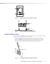
1. Hold the MLC face down. Use a small Philips screwdriver to remove the three
attachment screws (marked
a
in figure 6 on the next page) from the back of the
MLC, and keep them to replace later.
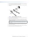
2. Lift the MLC off the faceplate (see figure 7 on the next page).
3. Place the MLC onto the new faceplate, aligning the MLC buttons with the openings in
the new faceplate and the three screw holes with the faceplate standoffs.
4. Replace the three screws removed in step 1 and tighten them.
MLC 52 MediaLink Controllers • Installation and Configuration 9