


Wiring the Control Connector
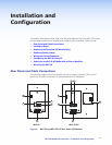
The display and source control connector allows you to connect cables for IR devices,
RS-232 devices (RS models only), and AC power to the MLC. The illustration below
shows the MLC control connector pin assignments that are described on the following
pages.
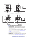
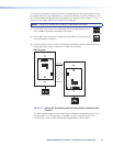
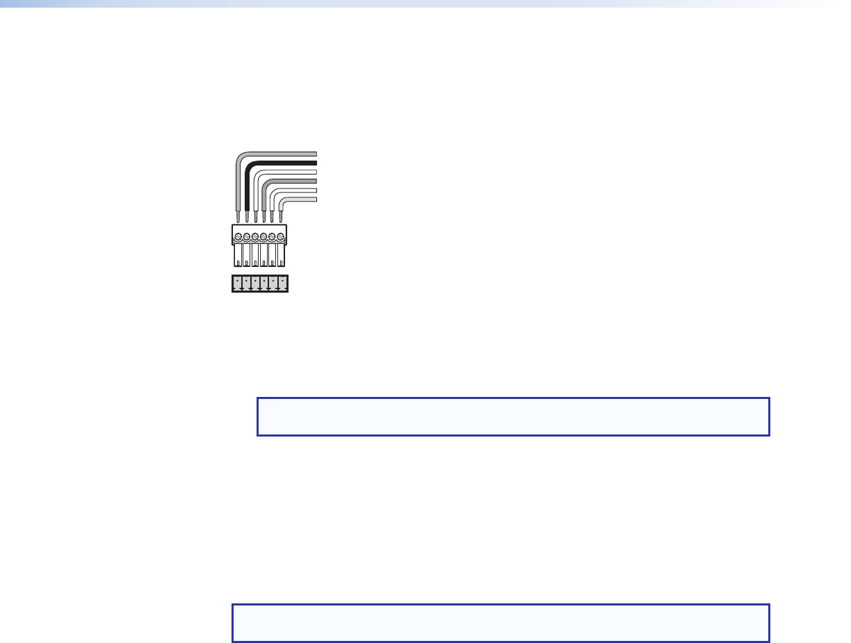
IR in
12 V DC in
F E D C B A
RS-232 Tx (RS models only)
IR out
Gnd
Gnd
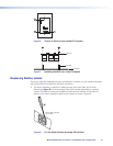
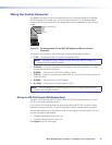
Figure 10. Pin Assignments for the MLC 52 Display and Source Control
Connector
The ports in this connector, from left to right, perform the following functions:
• F (Tx)
— Transmits the RS-232 signal for projector control.
NOTE: Although this port is present on both the IR and the RS models, it is
functional only on the RS models.
• E (IR out) — Used for connecting an IR emitter to issue IR commands. Up to two
emitters can be wired to this port.
• D (GND) — Ground for IR or RS-232 projector control
• C (IR in) — Used for connecting an optional IRL 20, so that an IR remote control can
control the MLC.
• B (GND) — Ground for the +12 VDC power
• A (+12 V) — Power input for the product (12 VDC)
NOTE: The two-gang MLC 52 IR VC and MLC 52 RS VC have the same control
ports as the one-gang models.
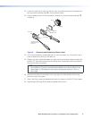
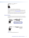
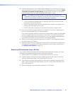
Wiring for RS-232 Control (RS Models Only)
The MLC 52 RS and the MLC 52 RS VC send out RS-232 commands via the Tx port
(pin F) for controlling a display device.
If you have an RS model and want to control the device via RS-232, connect a cable
between the device and this 3.5 mm, 6-pole direct insertion captive screw connector.
Wiring varies depending on the device model. In most cases, only the transmit (Tx) and
ground connections are needed.
• Connect the transmit wire to the F pin.
• Connect the ground wire to the D pin.
(See figure 11 on the next page.)
MLC 52 MediaLink Controllers • Installation and Configuration 12