


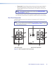

• The standard US MLC 52 model includes a one-gang black or white plastic faceplate,
which can be installed on a standard one-gang US electrical box that is at least
1.75 inches deep. A mounting bracket (“mud ring”) is also included.
• The US MLC 52 VC model includes a two-gang black or white plastic faceplate,
which can be installed in a standard US two-gang electrical box. A mud ring is also
included.
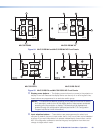
• The MLC 52 EU and MLC 52 VC EU models have two-gang RAL 9010 white or
brushed aluminum faceplates that can be installed on standard two-gang European
electrical boxes.
• The standard MLC 52 MK model includes a one-gang white or brushed aluminum
faceplate, which can be mounted on a 47 mm deep single MK electrical box.
• The MLC 52 VC MK model includes a two-gang white or brushed aluminum
faceplate, which can be mounted on a 47 mm deep double MK electrical box.
NOTE: EU and MK models must be mounted in an electrical box.
To prepare the site:
1. Choose a location that will allow cable runs without interference. Allow enough depth
for both the wall box and the cables. You may need to install the cables into the wall
or furniture before installing the controller. If using an electrical box to wall mount the
controller, locate a stud to which the box will be attached.
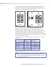
2. Measure and mark the portion to be cut out of the mounting surface.
For US models, use the appropriate template and faceplate dimensions provided
Templates for MLC 52 and MLC 52 VC (US Models) on page 64 as a guide to
measure and mark the area to cut out. If you are using a mounting bracket, see the
template that came with the bracket.
3. Cut out the opening in the wall or furniture.
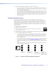
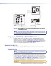
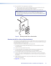
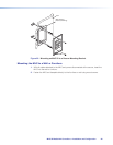
Mounting the MLC to an Electrical Box
You can mount the MLC 52 to an electrical box or a mounting bracket. For information on
mounting the electrical box itself, see Mounting an Electrical Box on page 63. To attach
a mounting bracket to a wall or furniture, see the instructions provided with the bracket.)
ATTENTION: If using an electrical box, ensure that it is grounded properly.
1. If you want to install a different faceplate, attach the MLC to the desired faceplate
using the provided screws (see Replacing the Faceplate (US Models Only) on
page 9).
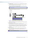
2. Disconnect power at the source.
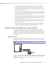
3. Pull the cables through the wall and electrical box, and connect all cables to the MLC.
4. Insert the MLC into the wall or furniture.
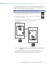
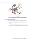
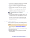
5. Secure the MLC to the wall box or mounting bracket with the provided machine
screws (as shown in figure 21 on the next page), or attach it directly to the furniture
with wood or metal screws.
MLC 52 MediaLink Controllers • Installation and Configuration 24