


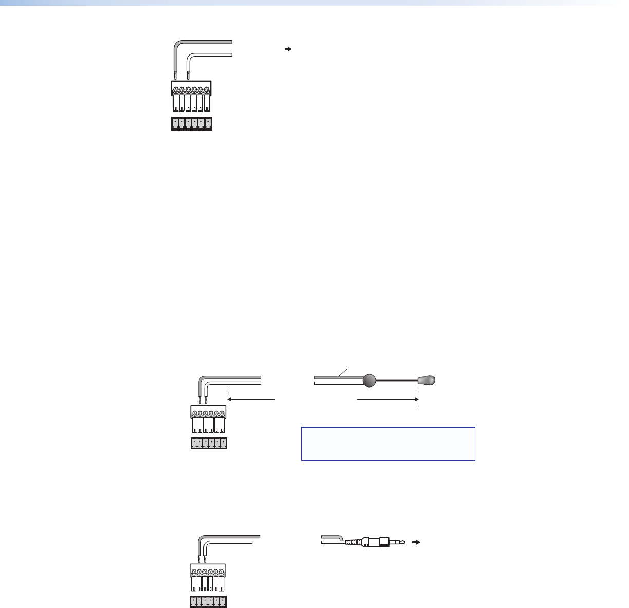
FIG_Wiring for RS-232
D Ground (Gnd)
F E D C B A
F Transmit (Tx)
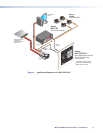
To the Display or Projector
RS-232 Port
R
S
-2
3
2
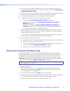
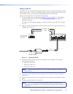
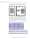
Figure 11. Wiring for RS-232 Control (RS Models Only)
Extron recommends using the CTL Series Comm-Link Control System Cable, available
in lengths of 500 feet (150 m) (non-plenum only) and 1000 feet (300 m) (plenum and
non-plenum) for this connection (see Recommended Cables on page 62 for ordering
information).
Guides for connecting and controlling specific models of display devices are available on
the Extron website. See the display device user guide for the device pin assignments in
order to determine which of the cables wires to connect to the MLC RS-232 pins.
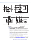
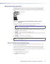
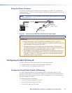
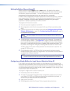
Wiring for IR Control
To control display or input devices via IR commands from the MLC, you can connect
Extron IR emitters to the IR Out pin of the control connector. Up to two IR emitters can be
connected via this connector at one time. Wire the connector as shown in the following
illustrations.
MLC 52
Control
Connector
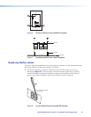
For the IR Emitter Only
IR
Emitter
White Striped Wire Only
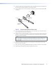
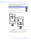
For a Wired Projector
Remote Port
IR
MLC 52
Control
Connector
IR
Demodulated IR
Ground
Modulated IR
Ground
100 Feet (30.5 m) Maximum
Connect 1 or 2
IR Emitters (max.)
(#70-283-01).
NOTE: Place the head of each IR Emitter
over or directly adjacent to the IR receiver
for the controlled device.
To the Wired Remote
Port of the Projector
(Connector type and
pin configurations may
vary depending on the
projector model.)
D
E
D
E
F E D C B A
F E D C B A
Figure 12. Wiring the Control Connector for IR
MLC 52 MediaLink Controllers • Installation and Configuration 13