


Mounting an Electrical Box
If you want to install the MLC 52 or MLC 52 VC (US models) in an electrical box (in a wall
or in furniture), install the box as described below.
NOTE: These instructions are for US models only. To mount an electrical box for an
EU or MK model, follow the directions provided with the box by its manufacturer.
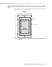
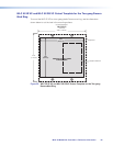
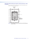
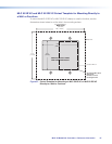
1. See the appropriate template diagram in Templates for MLC 52 and
MLC 52 VC (US Models) on page 64, to find out the dimensions of the opening
required for the size of the wall box or mud ring that you are using.
2. Using a ruler or tape measure and a soft pencil, draw guidelines on the installation
surface (wall or furniture) in the desired orientation and location where the opening for
the bracket or wall box will be cut.
ATTENTION: The template diagrams in this guide are not to scale. Do not trace
them or use them as patterns on the installation surface. Use these diagrams
only for reference to obtain the dimensions of the hole that needs to be cut.
Use a ruler to measure and draw the cutting guidelines.
3. Cut out the wall or furniture material inside the marked area.
4. Check the opening size by inserting the wall box or mounting bracket into the
opening. The equipment should fit easily into the opening. Enlarge or smooth the
edges of the opening if needed.
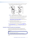
5. Feed cables through the electrical box punch-out holes, and secure them with cable
clamps to provide strain relief.
6. Ground the electrical box.
7. Exposed cable shields (braided or foil) are potential sources of short circuits. Trim
back or insulate shields with heat shrink.
CAUTION: To prevent short circuits, cut back the outer foil shield to the point
where the cable exits the cable clamp. Both braided and foil shields should be
connected to an equipment ground at the other end of the cable.
MLC 52 MediaLink Controllers • Reference Information 62