


Setting up the Analyzer
Limits Adjustments20
20-15
7
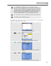
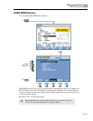
Press Function key F5 – BACK to return to the SETUP entry menu.
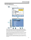
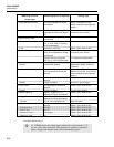
Setup of Monitor Limits, a survey of adjustments.
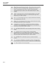
Limits Adjustments
Voltage 2 Probability percentages (100 % and adjustable):
each with adjustable upper and lower limit.
Harmonics For each harmonic 2 Probability percentages (100
% and adjustable): each with adjustable upper limit.
Flicker Weighing curve (lamp type). 2 Probability
percentages (100 % and adjustable): adjustable
percentage with adjustable upper limit.
Dips (*) Reference voltage (Nominal or Sliding). Threshold,
hysteresis, allowed number of dips/week.
Swells (*) Reference voltage (Nominal or Sliding). Threshold,
hysteresis, allowed number of swells/week.
Interruptions (*) Threshold, hysteresis, allowed number of
interruptions/week. Reference voltage is Nominal.
Rapid Voltage Changes (*) Voltage tolerance, Steady time, Minimum step,
Minimum rate (V/s), allowed number of
events/week.
Unbalance For each harmonic 2 Probability percentages (100
% and adjustable): adjustable percentage with
adjustable upper limit.
Frequency 2 Probability percentages (100 % and adjustable):
each with adjustable upper and lower limit.
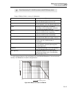
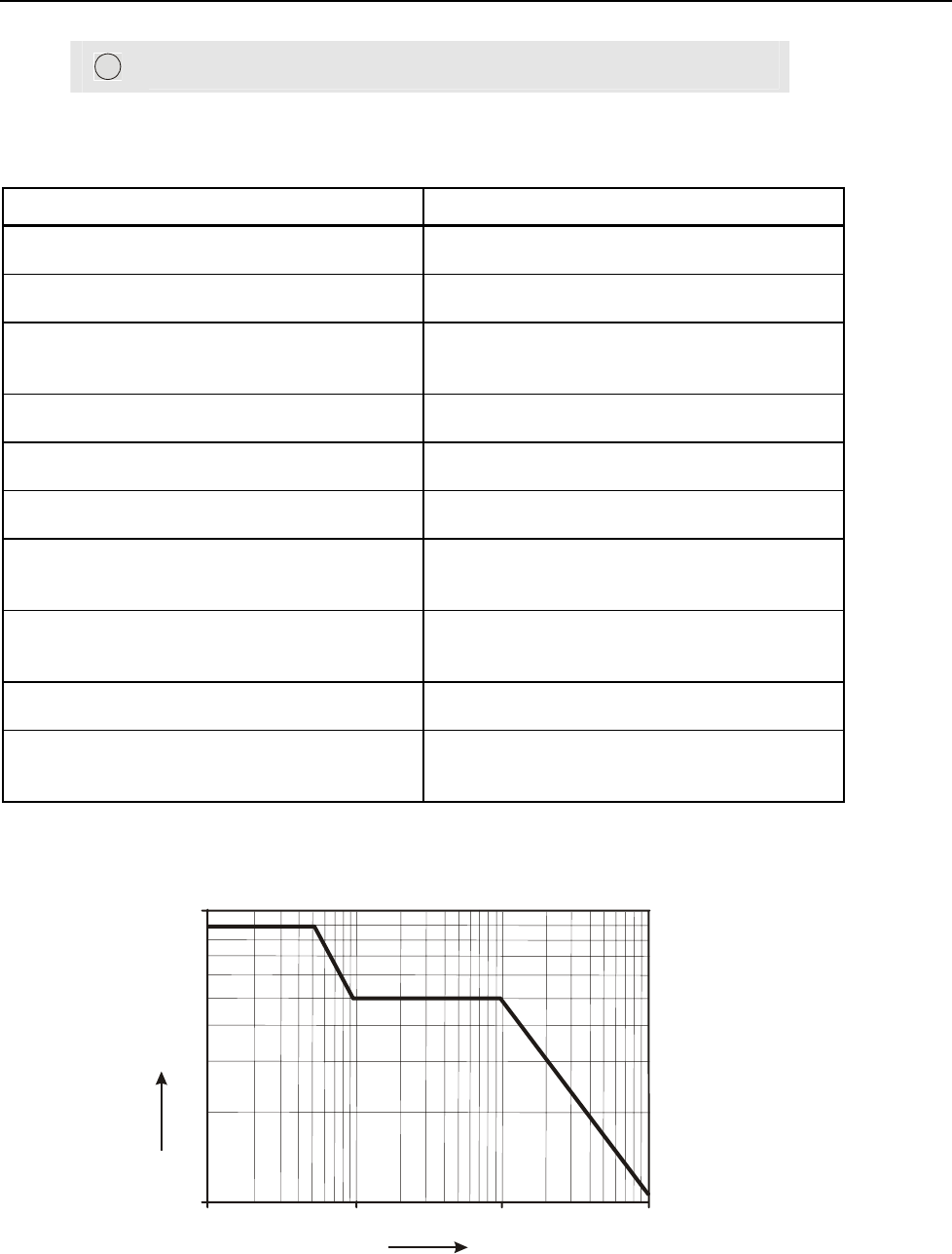
Mains Signaling 2 Adjustable frequencies. For each frequency 2
probability percentages (100 % and adjustable):
adjustable upper limits (**).
(*): setups that are also valid for measuring mode Dips & Swells. Events per week is used for Monitor only.
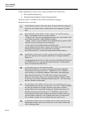
(**): when changing frequency, limits automatically follow the EN50160 ‘Meisterkurve’, but can also be set
manually. The ‘Meisterkurve’ is shown in the figure below.
0,1 1
1
10
10
100
Frequency in kHz
Voltage level in percent
Figure 20-2. Meister Kurve acc. to EN50160