


6-1
Chapter 6
Input Connections
Introduction
This chapter explains how to make connection to the power distribution system under test
and how to adjust the Analyzer settings.
Check that the Analyzer setup meets the characteristics of the system under test and the
accessories that are used. This concerns:
• wiring configuration
• nominal frequency
• nominal voltage
• properties of voltage leads and current clamps
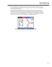
The actual setup is shown in the welcome screen that appears after power up. To change
the setup, refer to Chapter 20.
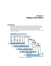
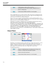
Input Connections
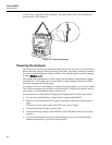
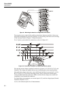
The Analyzer has 4 BNC-inputs for current clamps and 5 banana-inputs for voltages.
Self-adhesive decals are supplied corresponding to wiring color codes used in the USA,
Canada, Continental Europe, the UK, and China. Stick the decals that fit to your local
wiring codes around the current and voltage inputs as shown in Figure 6-1.