


Input Connections
Input Connections 6
6-3
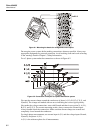
Before making any measurements, set the Analyzer up for the line voltage, frequency,
and wiring configuration of the power system you want to measure. This is explained in
Chapter 20, General Settings.
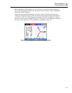
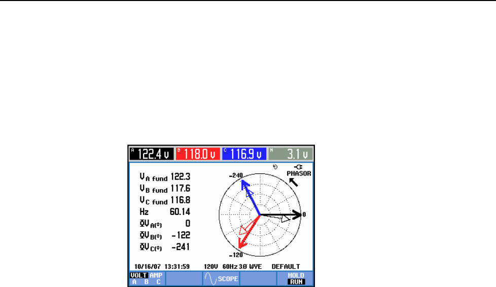
Scope Waveform and Phasor display are useful to check if voltage leads and current
clamps are connected correctly. In the vector diagram the phase voltages and currents A
(L1), B (L2), and C (L3) should appear in sequence when observing them in clockwise
direction as shown in the example in Figure 6-3 (This type of vector diagram is displayed
after reset of the Analyzer to factory defaults as explained on page 4-4).
Figure 6-3. Vector diagram for correctly connected Analyzer