


Appendix E UPS Controller E-3
ON:Indicates contacts are closed
OFF: Indicates contacts are open
Note1: Use a UPS capable of normal battery power supply operation for at least 10 to 60 seconds after this signal is turned on.
Note2: Use a UPS capable of normal battery power supply output without turning on the *ACOFF in an instantaneous commercial AC
power failure lasting two seconds or less.
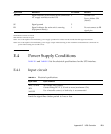
E.4 Power Supply Conditions
TABLE E-2 and TABLE E-3 list the electrical specifications for the UPS interface.
E.4.1 Input circuit
Limit the signal-line chatter period to 1ms or less.
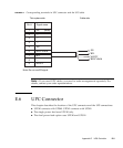
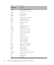
*ACOFF Signal indicates power failure at the commercial
AC supply connector to the UPS
9Normal: OFF
Power failure: ON
(Note2)
SG Signal ground 5
ER Signal indicates the main unit is running
(Equipment Ready)
1 Do not connect to ER
signal pin.
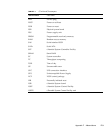
TABLE E-2 Electrical specifications
Signal name Input conditions
*BPS/*UALM No voltage relay contact
Contact rating DC 12 V, 10 mA or more (maximum 0.5A)
Use of metallic contact, or lead relay is recommended.
*BTL
*ACOFF
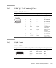
Signal name Definitions Pin number Remarks