


4-1
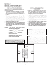
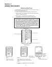
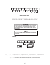
Figure 4-1. REMOVING THE TOP COVER
Unit Cover (Middle)
Mounting Screw
Holes
Keypad Panel
Unit Cover (Top)
Top Cover Screw
Removing Top Cover
To access Main and Control Circuit Terminals remove the top
cover as follows (see Figure 4-1):
1. Loosen the screw located at the bottom of the top cover.
2. Press upward on the bottom of the top cover (see arrows
Figure 4-1 step 2) and lift off.
3. See Figure 4-1 for the location of the Main Circuit
Terminal Block and the Control Circuit Terminal Block.
Section 4
WIRING PROCEDURES
WARNING: Some printed circuit boards and Drive com-
ponents may contain hazardous voltage levels. If LED
light "CRG" on the Base Driver Board is illuminated,
hazardous voltages are present in the Drive circuit boards.
Remove and lock out power before you disconnect or
reconnect wires, and before you remove or replace fuses
and circuit boards. Do not attempt to service the Drive
until the "CRG" indicator has extinguished and the bus
voltage has discharged to zero volts.
Control
Circuit
Terminal
Block
Step 2:
Press Upward at the locations indi-
cated by the arrows to remove the top
cover.
Main Circuit
Teminal Block
Drive
Charge "CRG" Lamp
Heat Sink
and Mounting Tabs
Step 1:
Loosen Top Cover
screw. (1 to 2 turns)
→
→