


1-3
with the NEC or Canadian Electrical Code. The
connection shall be made by a UL listed or CSA
certified closed-loop terminal connector sized for
the wire gauge involved. The connector is to be
fixed using the crimp tool specified by the
connector manufacturer.
Do not perform a megger test
between the Drive terminals or on the control
circuit terminals.
The Drives are an IGBT drive
which develops an adjustable frequency via pulse
width modulation. While this does not present a
problem on 200-240 VAC applications, it may on
380-480 VAC applications. When using the
Drives on 380-480 VAC, get the motor
manufacturer's approval that his insulation system
can withstand the voltage spikes (up to twice the
dc bus voltage 2 x 621 VDC for a 480 VAC power
source of the Drive, in conjunction with the long
motor cable lengths). If the insulation system
does not meet this limit, utilize a RLC filter.
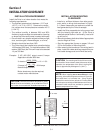
Because the ambient
temperature greatly affects Drive life and
reliability, do not install the Drive in any location
that exceeds the allowable temperature. Leave
the ventilation covers attached for temperatures
of 40 degrees C or below, and remove the
ventilation port side and top covers for
temperatures of between 40 (104° F) and 50
(122° F) degrees C. If the covers need to be
removed, another type of enclosure may be
required for safety purposes.
If the Drive’s Fault Alarm is
activated, consult the TROUBLESHOOTING
section of this instruction book, and after
correcting the problem, resume operation. Do
not reset the alarm automatically by external
sequence, etc.
Be sure to remove the desic-
cant packet(s) when unpacking the Drive. (If not
removed these packets may become lodged in
the fan or air passages and cause the Drive to
overheat.)
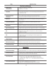
CAUTIONS
This product is suitable for use
on a circuit capable of delivering not more than
1,000 (1HP or less) or 5,000 (2 HP or more) rms
symmetrical amperes.
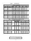
AC input fuses to be customer supplied and may
be branch circuit protection fused. The maximum
allowance fuse ratings per TABLE 4.
Do not connect power supply
voltage that exceeds the standard specified
voltage permissible. If excessive voltage is
applied to the Drive, damage to the internal
components will result.
Do not connect power supply to
the output terminals (U, V, W). Connect power
supply only to the power terminals (L1, L2, L3).
Do not connect power supply to
the breaking resistor connection terminals (P (+),
DB). Never short-circuit between P (+) – DB
terminals, and do not connect any resistance with
an ohm and/or wattage value less than standard
application breaking resistor.
Do not connect a power supply
to the control circuit terminals (except 30A, B, C,
maximum rating 250 volts, 0.3A ac/dc).
For RUN and STOP, use the
FWD-CM (forward) and REV-CM (reverse)
terminals. Do not use a contactor (ON/OFF)
installed on the line side of the Drive for RUN and
STOP.
Do not use a switch on the
output side of the Drive for ON/OFF operation.
Do not connect power factor
correcting capacitors on the output side of the
Drive.
Do not operate the Drive
without the ground wire connected. The motor
chassis should be grounded to earth through a
ground lead separate from all other equipment
ground leads to prevent noise coupling. The
grounding connector shall be sized in accordance