


1-4
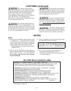
UL/CSA Drive Caution Label
Use 60/70°C copper wire only. Use Class 1 wire only.
Suitable for use on a circuit capable of delivering not more than 1,000
(1HP or less) or 5,000 (2 HP or more) rms symmetrical amperes.
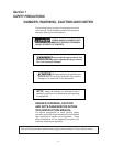
WARNING: HAZARD OF ELECTRICAL SHOCK. DISCONNECT INCOMING
POWER BEFORE WORKING ON THIS CONTROL.
ADVERTISSEMENT: RISQUE DE CHOC ELECTRIQUE COUPER
L'ALIMENTATION AVANT LE DEPANNAGE DE CETTE COMMANDE.
CAUTION: DANGEROUS VOLTAGE EXIST UNTIL CHARGE "CRG" LIGHT IS OFF.
ATTENTION: PRESENCE DE TENSIONS DANGEREUSES TANT QUE LE
VOYANT N'EST PAS ETEINT.
WARNING: MORE THAN ONE LIVE CIRCUIT. SEE DIAGRAM.*
AVERTISSEMENT: CET EQUIPEMENT RENFERME PLUSIEURS CIRCUITS
SOUS TENSION. VOIR LE SCHEMA. SA523154-01
*See diagram on page 4-6.
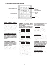
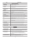
CAUTIONS (continued)
NOTE:
① When terminal operation mode (Function code
F_02 setting is 1) - RUN and STOP are being
controlled by a maintained contact (e.g., selector
switch, toggle switch, etc.) which is connected
between the terminal CM and FWD or REV:
• Closing/opening the maintained contact starts/
stops the Drive.
➁ Function code F_02 setting can be changed only
when connection between the terminals CM and
FWD or REV is open. (i.e. STOP MODE).
Drive ships with shorting bar between
terminals FWD-CM.
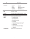
NOTES
AC induction motors require
that they be sized based on the applications speed
range and associated torque requirements for the
motor-Drive system; this is to avoid excessive
motor heating. Observe motor manufacturer's
recommendations when operating any ac induction
motor with the Drive. Also observe motor
manufacturer's recommended voltage/torque boost
at lower operating frequencies.
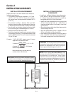
The available power source con-
nected to the Drive is not to exceed 500KVA. If the
ac power source is greater than 500KVA and the
Drive's rated (HP) is less than 10% of the power
source's KVA; ac line reactors will have to be installed
in L1, L2 & L3 power leads of the Drive.
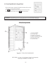
The Drive must be mounted on
a building or enclosure wall that is constructed of
heat resistant material. While the Drive is operat-
ing, the temperature of the Drive's cooling fins can
rise to a temperature of 90°C (194°F.)
If the Drive protective function
is activated, consult Section 8 "Troubleshooting",
and after correcting the problem, resume opera-
tion. Do not reset the alarm automatically by
external sequence, etc.
Be sure to provide fuses, as
specified on "Application of Wiring And Equipment"
in Section 4, on line terminals of Drive. Provide
power line disconnect or contactor as needed.
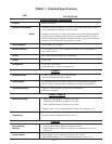
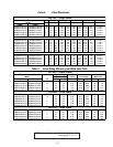
➂ Total wiring between the Drive and the motor must
not exceed the length shown below.
➃ Error in current detection may increase when;
a) A specially designed motor is used.
b) A Drive's capacity is 2 Hp ratings or greater than
the motor capacity.
Function 200V Series 400V Series
F_12 data
Hp
1/4 1/21235 1/2 1 2 3 5
F_12 = 0, 1, 2 or 3 538 ft. 754 ft.
F_12 = 4 – 15
1076 ft.
213 ft.
1076 ft.