4-2
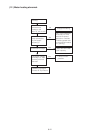
Control Circuit Wiring
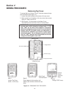
Drive is wired at shipment for operation and frequency
setting through the keypad panel (frequency is set at 60
Hz.)
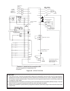
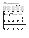
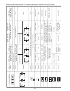
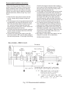
– See Figure 4-2, and 4-4 for wiring connections.
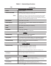
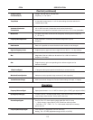
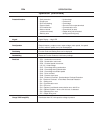
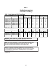
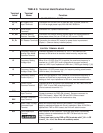
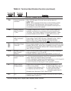
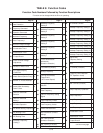
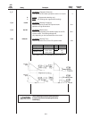
– See TABLE 5 for description of all terminals.
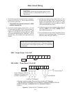
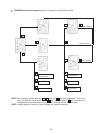
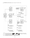
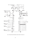
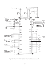
Make wire connections as shown in Figure 4-4 through 4-6
for desired mode of external operation through Control
Circuit Terminals.
CAUTION: The Control Circuit Terminal wiring should be
kept as far away as possible from the main power wiring to
prevent operational error due to noise interference. Never
install both types of wiring in the same duct or conduit. (A
separation distance of 4 inches [10 centimeters] or more is
recommended.) If the control circuit wiring must cross the
main power wiring, it should cross at a right angle.
CAUTION: Use shielded or twisted wire for the control
circuit wiring (wiring should be as short as possible, i.e. 65
feet or less [20 meters.]) Connect outer covering of the
shielded wires to the Drive ground terminal and leave the
other end open, but taped with electrical insulating tape.
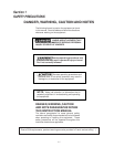
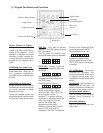
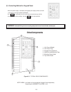
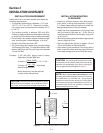
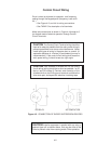
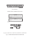
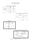
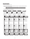
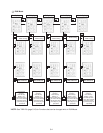
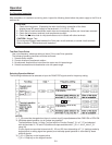
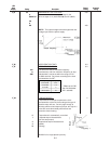
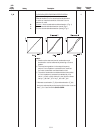
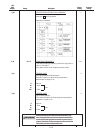
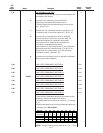
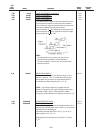
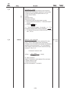
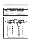
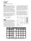
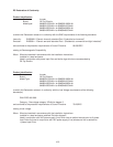
DC RELAY
AC CONTACTOR
Figure 4-2. CONNECTION OF SURGE SUPPRESSION DEVICES
CAUTION: Install a suppressor in parallel with any relay or
solenoid type coil as shown above, that may be close to the
Drive to prevent noise from causing erratic Drive operation.