


10-2
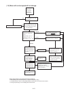
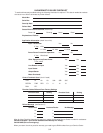
Recommended Installation Instructions
These instructions must be followed in order to
conform to the EMC Directive. Follow the usual
safety procedures when working with electrical
equipment. All electrical connections to the filter,
Inverter, and motor must be made by a qualified
electrical technician. (Refer to Fig.2, Fig. 3, and
Fig.4)
1. Check the filter rating label to ensure that the
current, voltage rating, and part number are
correct.
2. The back panel of the wiring cabinet board should
be prepared for the mounting dimensions of the
filter. Care should be taken to remove any paint
etc. from the mounting holes and face area
around the hole of the panel. This will ensure the
best possible earthing of the filter.
3. The filter should be securely mounted in position,
and the Inverter mounted to the front of the filter
with the screws provided.
4. Connect the incoming main supply to the filter
terminals marked “LINE” and any earth cables to
the earth stud provided. Fit the Input Ferrite Ring
(if two ferrite rings are required, refer to table 1),
and connect the filter terminals marked “LOAD” to
the main input of the of the Drive using a short
length of appropriate gauge wire.
5. Fit the output Ferrite Ring as close to the Inverter
as possible and connect the motor. Armored or
screened cable should be used with the 3 phase
conductors passing twice through the center of
the Output Ferrite Ring. The earth conductor
should be securely earthed at both the ground
terminal in the cabinet and at the motor ends. The
screen should be connected to the enclosure.
6. It is important that all lead lengths are kept as
short as possible and that incoming mains and
outgoing motor cables are kept well separated.
7. Segregate power cables from control wiring, as
thoroughly as possible, and avoid parallel cable
run to minimize ‘noise coupling’. When ever runs
of power and control cable must cross, try to
achieve this at right angles.
8. Micro-$aver II Drive should be installed, and are
designed to operate, with an electrically -
shielded metal enclosure.
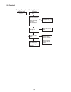
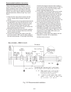
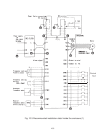
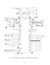
Fig. 10-2 Recommended installation
Drive