


LED
Data Factory Customer
Display Setting Description Setting Setting
6-5
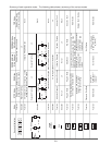
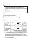
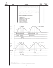
*F_09 FMA (Analog Meter) VOLTAGE ADJUSTMENT 85
This function adjusts the full scale voltage level of
the analog voltage signal from the FMA terminal.
0 0: Approx. 6.5V
to
99 99: Approx. 10.5V
NOTE: This function is only active if F_40 = 0 (FMA
terminal output).
Select the type of signal output from the FMA
terminal by means of F_41 (FMA terminal function
selection).
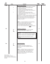
*F_10
MOTOR POLES 4
This sets the number of poles of the motor being used
for synchronous speed display.
2 : 2 poles 6: 6 poles 10 : 10 poles
4 : 4 poles 8: 8 poles 12 : 12 poles
Example: If running a 4-pole motor at 60 Hz, the
display will be 120 x 60 ÷ 4 = 1800.
If running a 4-pole motor at 50 Hz, the display will
be 120 x 50 ÷ 4 = 1500.
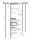
*F_11 0.01
LINE SPEED DISPLAY COEFFICIENT 0.01
to This sets the display coefficient for displaying the
200.0 line speed [m/min.]
Display value [m/min.]= Output frequency [Hz] x
display coefficient
*F_12 0
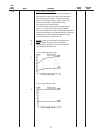
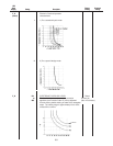
MOTOR SOUND ADJUSTMENT 2
to (Carrier Frequency)
15 This adjusts the carrier frequency of the Drive
within the range of 0.75 to 15 kHz. The acoustic
and electromagnetic noise generated by the motor
increases as the carrier frequency is decreased.
If set to 0, the carrier frequency will be set to 0.75
kHz (maximum noise). The adjustment from 1 to
15 kHz can be carried out in 1 kHz steps.
NOTE: The higher the carrier frequency, the
greater the adverse affects on the motor
insulation.
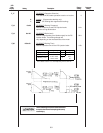
The value can be adjusted to one
of 100 settings within this range.
Display Coefficient Setting Step
Setting Range
0.01 to 9.99 0.01
10.0 to 200.0 0.1