


10-1
Section 10
CE MARK
Electromagnetic Compatibility (EMC)
General
In accordance with the provisions described in the
European Commission Guidelines Document on
Council Directive 89/336/EEC, GE Fuji Electric Co.,
Ltd. has chosen to classify the 1 phase, 240 VAC,
3 phase 415 VAC range of Drives as “Complex
Components”. Classification as “Complex
Components” allows a product to be treated as an
“apparatus”, and thus permits compliance with the
essential requirements of the EMC Directive to be
demonstrated to both an integrator of Micro-$aver II
Drive and to his consumer or the installer and user.
Micro-$aver II Drives up to 5 Hp are supplied ‘EC -
marked’, signifying compliance with EC Directive 89/
336/EEC when fitted with specified filter units
installed and earthed in accordance with this sheet..
This specification requires the following
performance criteria to be met.
Immunity : EN50082 - 2
Emissions : EN50081 - 1
RFI Filters
It is strongly recommended that the appropriate
Micro-$aver II Drive input filter be used to limit RF
current flowing into the main supply circuit. (Refer to
Table 10-1.) Without an input filter a Micro-$aver II
Drive installation may not meet statutory
requirement. Micro-$aver II Drive contain high -
power semi - conductor devices which are switched
at high speeds to synthesize a near - sinusoidal
current waveform across the frequency range of
output. Rapidly changing voltages and currents will
generate some degree of electromagnetic emission.
Emissions will be predominantly conducted through
the motor and the main supply cables, although
some radiated emissions will be detected in close
proximity to the drive system. It is essential that
precautions are taken at the design stage, and at
the time of installation, to prevent radio frequency
interference. (RFI) from the drive system affecting
sensitive equipment in close proximity.
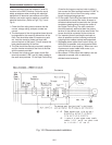
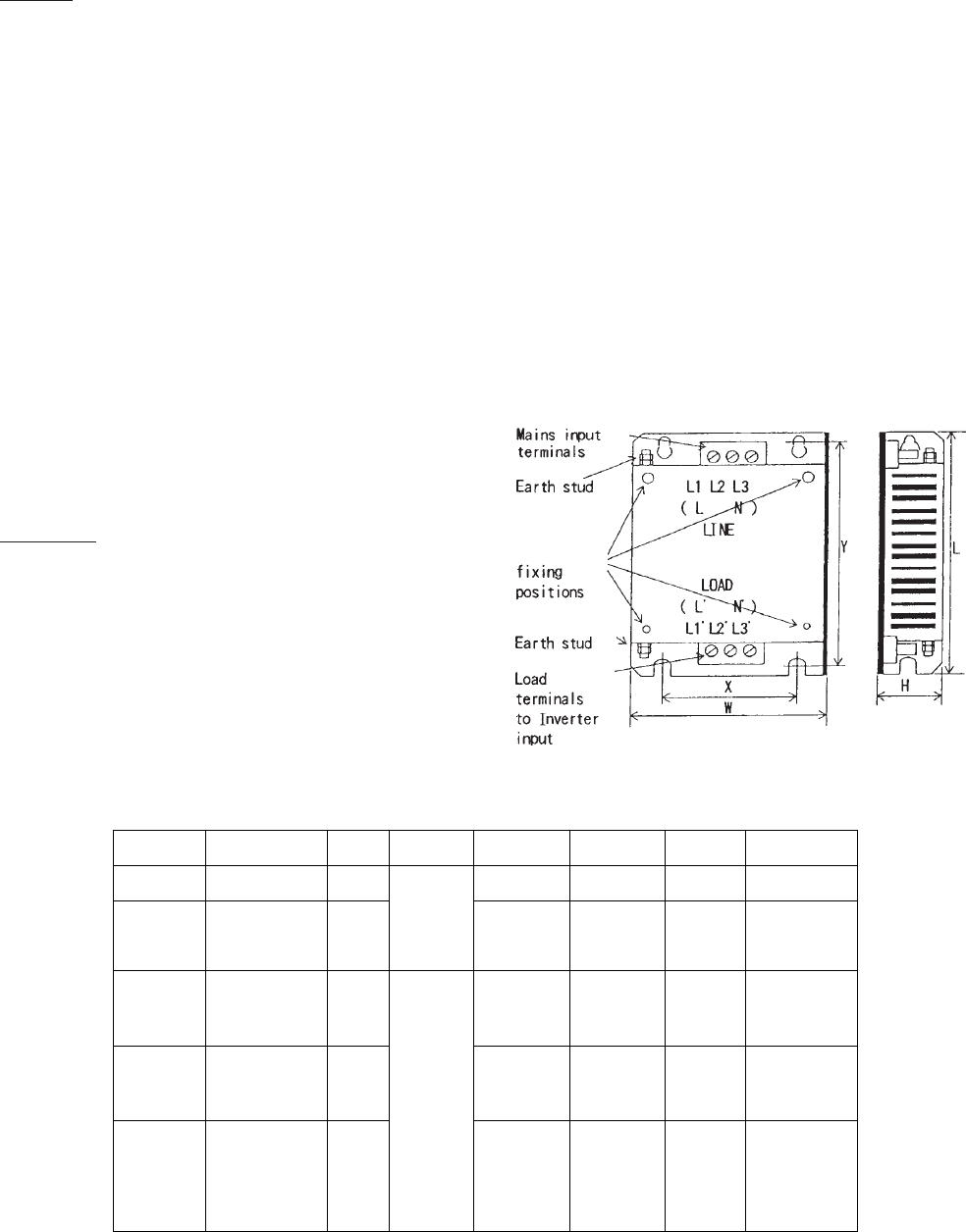
The RFI filters range are designed especially for the
Micro-$aver II Drive and help to ensure EMC
compliance of machinery as installations using
Inverters. The Drives may be mounted on top of the
filter using integral fixing positions, the intention
being that valuable space inside wiring cabinets
may be saved. (Refer to Fig. 10 - 1 and Table 10- 1)
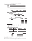
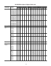
Table 10-1 RFI Filters Dimensions - Conforms to EN55011 Class B
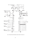
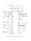
Fig. 10-1 RFI Filters
Drive
Filter Applied Rated Max Rated Dimensions Mount Inverter Required
Part No. Drive Current Voltage L,W,D mm Dim. X, Y Fixings Sub FIlter
AFL-0.2 E9-7 6KM$221F25N1A1 3A 200x110x34 84x186 M4x12(4) Ferrite Ring
6KM$221F25X4A1 1 Phase OC1x1pcs
EFL-0.75 E9-7 6KM$221F50N1A1 10A 240 VAC 200x145x40 118x186 M4x12(4) Ferrite Ring
6KM$221F50X4A1 OC1x1pcs
6KM$221001N1A1
6KM$221001X4A1
EFL-2.2 E9-7 6KM$221002N1A1 23A 200x205x40 178x186 M4x12(4) Ferrite Ring
6KM$221002X4A1 OC1x1pcs
6KM$221003N1A1
6KM$221003X4A1
EFL-0.75 E9-4 6KM$243F50N1A1 3A 3 phase 200x145x45 118x186 M4x12(4) Ferrite Ring
6KM$243F50X4A1 415 VAC OC1x1pcs
6KM$243001N1A1
6KM$243001X4A1
EFL-4.0 E9-4 6KM$243002N1A1 12A 200x205x45 178x186 M4x12(4) Ferrite Ring
6KM$243002X4A1 OC1x1pcs
6KM$243003N1A1
6KM$243003X4A1
6KM$243005N1A1
6KM$243005X4A1