


8-1
Section 8
TROUBLESHOOTING
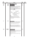
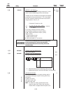
TABLE 8: Fault Condition Description and Operation
The following Drive protection functions have been incorporated in the basic Drive software and will be indicated in the
LED display. Use F_29 to check fault history.
Protective LED
Function Display
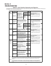
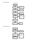
Overcurrent During OC1
protection Acceleration
During OC2
Deceleration
Short circuit, During OC3
Ground fault constant
speed
operation
Momentary LU • Drive output frequency drops to 0.0 Hz
power failure If the "restart after momentary power
failure" mode is selected, operation
Undervoltage will restart automatically when power
protection is restored.
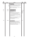
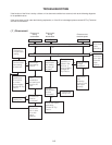
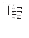
Overvoltage During OU1
protection Acceleration
During OU2
Deceleration
During OU3
constant speed
operation
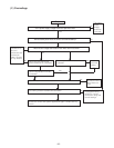
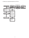
Drive OH1
overheating
External alarm OH2
input
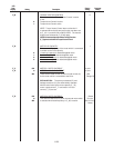
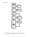
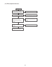
Electronic OLU
overload
OL
Memory Error Er1
Communication Er2
Error
2
)
CPU error Er3
Optional Er4
circuit board
communication
error
Option Er5
problem
Operating Detects Drive operating procedure error Er6
Proc. error during Drive startup. FWD or REV
connected to terminal CM at time of main
power being applied to Drive.
Stop keypad in remote operation
Output wiring Er7
error
Protects the Drive if
the Drive output
current momentarily
exceeds the
overcurrent detection
level. Protects the
Drive from
overcurrent resulting
from an output phase
-
to-phase or phase-to-
ground short circuit.
Function Explanation Protective OperationDisplay
Avoids loss of control of the Drive
caused by drops in the power supply.
NOTE: Operation will continue if the
momentary power failure or under-
voltage period is less than 15 msec.
• Drive output frequency drops to 0.0 Hz
• Motor coasts to a stop
• Alarm terminals 30A, 30B, and 30C
are activated
• Alarm signal is maintained internally
until alarm reset command is given
1)
Protects the Drive if
momentary
overvoltage
(regenerative
overvoltage) exceeds
the overvoltage
detection level.
• Drive output frequency drops to 0.0 Hz
• Motor coasts to a stop
• Alarm terminals 30A, 30B, and 30C
are activated
• Alarm signal is maintained internally
until alarm reset command is given
1)
• Drive output frequency drops to 0.0 Hz.
• Motor coasts to a stop
• Alarm terminals 30A, 30B, and 30C
are activated
• Alarm signal is maintained internally
until alarm reset command is given
1)
Detects overheating of the Drive
caused by an overload, cooling
fan problem or abnormal ambient
temperature.
Acts as an external alarm to stop
output. If protective device such
as the overload relay is connected
between THR and CM terminals
switches from ON to OFF.
• Drive output frequency drops to 0.0 Hz.
• Motor coasts to a stop
• Alarm terminals 30A, 30B, and 30C
are activated
• Alarm signal is maintained internally
until alarm reset command is given
1)
Protects semiconductor devices
such as the IGBT from overloads.
Protects a standard 4-pole motor
or a forced air cooled motor from
overloads even if an overload
relay is not connected.
• Drive output frequency drops to 0.0 Hz.
• Motor coasts to a stop
• Alarm terminals 30A, 30B, and 30C
are activated
• Alarm signal is maintained internally
until alarm reset command is given
1)
Operates when a memory error
occurs due to a data writing error,
Displayed when a communication
error occurs between the Drive
and the keypad panel.
Stops the Drive when an error is
detected in the CPU.
Displayed when there is a
communication "checksum error"
or interruption of communication
between the Drive and the option
circuit board.
Displayed when a link error etc. is
detected.
Stops the Drive when it is
detected that the output wiring is
not connected during automatic
tuning.
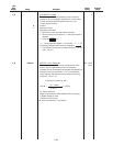
Alarm signal hold
When a protection function has been activated and the alarm signal is output; if an AC contactor provided on the
power supply side is switched off, and the Drive's control power is not supplied, the alarm signal will not be
retained.
During external terminal operation (F02=1), the Drive will continue running without an alarm being tripped even if
error Er2 is displayed. If communication is restored, the Er2 display will disappear, and normal operation will
resume.
NOTE 1
N
O
TE 2
OC1,
OC2,
OC3
OU1,
OU2,
OU3
OH1,
OH2,
OL,
OLU
LU
Er1,
Er2,
Er3,
Er4,
Er5,
Er6,
Er7