


4-3
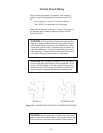
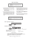
Main Circuit Wiring
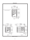
1. Connect the ground terminal as shown in the appro-
priate view of Figure 4-3. (Do not operate without
the unit being grounded.)
— The ground wire must be minimum 14 AWG
and short as possible
2. Connect the power supply wires to the L1, L2, and
L3 terminals of the Main Circuit Terminal Block as
shown in the appropriate view of Figure 4-3. (See
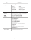
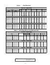
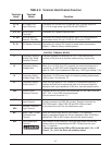
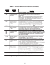
TABLE 5 for description of all terminals and TABLE
4 for recommended wire sizes.) Note that L1 and L2
terminals only, are available on single phase input
models.
3. Connect the 3-phase motor wires to the U, V, and
W terminals of the Main Circuit Terminal Block as
shown in the appropriate view of Figure 4-3. (See
TABLE 5 for description of all terminals and TABLE
4 for recommended wire sizes.)
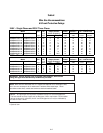
4. Suitable for use on a circuit capable of delivering not
more than 1000A (1 HP or less) or 5000A (2 HP or
more) RMS symmetrical.
5. AC input fuses are to be customer supplied and may
be branch circuit protection fuses. The maximum
allowance fuse rating per TABLE 4.
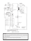
3–Phase Motor
50/60 Hz, 3–Phase AC
240V – Single Phase 1/4 to 3 HP
CAUTION: Be sure that the power supply is never
connected to the U, V, W terminals or the P (1), P (+),
DB terminals.
NOTE:
Motor will rotate counterclockwise when viewed from
the shaft end when connected normally. If the motor rotates in
reverse direction, interchange any two of the U, V, or W terminal
connections.
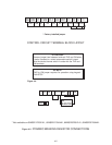
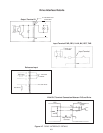
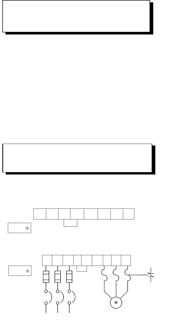
Figure 4-3. MAIN CIRCUIT TERMINAL LAYOUT
✟ Factory installed jumper (Remove when installing DC Reactor)
* The DB resistor connection is not available on models 6KM$221F25X1A1,
6KM$221F25A4A1, 6KM$223F25X1A1, 6KM$223F25A4A1.
# Optional
CB
Fuses: Rating per TABLE 4
Reference UL power circuit
protection requirements.
Thermal Relay
#
L1 L2 L3 P1 P(+) DB U V W
E (G)
L1 L2 P1 P(+) DB* U V W
E (G)
✟
✟
230 & 480V – Three Phase 1/4 to 5 HP