


4-6
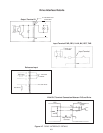
CAUTION:
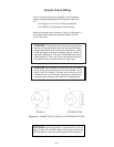
1. The Control Circuit Terminal wiring should be kept as far as possible from the main circuit wiring to prevent
operation error due to noise interference. Never install them in the same duct or conduit. A separation distance
of 4 inches or more is recommended. If the control circuit wiring must cross the main circuit wiring, make sure
it crosses at a right angle.
2. Use shielded wire for the control circuit wiring, which should be as short as possible (66 feet or less). Connect
shield to the Drive ground terminal and leave the other end open but taped.
3. Install a surge protector in parallel with any magnetic contactors, solenoids, relays or timer coils which are close
to the Drive.
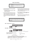
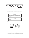
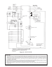
Figure 4-6. WIRING DIAGRAM
#
X4(HLD)
RST
BX
Y1
PLC
PROGRAMMABLE LOGIC
CONTROL POWER
ALARM RELAY OUTPUT
FUSE
DIGITAL METER
BRAKING RESISTOR
1/2 TO 5HP #
P1
DC REACTOR #
DO NOT CONNECT
TO CM
✟
1 or 3PH
50/60 Hz
230/480 Vac
(Based on
Model selected)
* Terminal 11 should not be connected to CM.
✟ L3 not supplied on single phase units.
# Optional
BRAKING RESISTOR
THERMAL SWITCH
GROUND
DISCONNECT/
CIRCUIT
BREAKER #
ANY ADDITIONAL NORMALLY
CLOSED PROTECTIVE
INTERLOCKS SHOULD BE
ADDED IN SERIES