2 - 2 Quick Check® SV Series User’s Guide
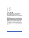
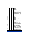
9 - Reserved
10 - Reserved
11 - GND
12 - +5 VDC power in
13 - Power GND
14 - GND
15 - Output Port 5
+ 5 VDC Power Input
The SV Series requires + 5 Volts DC, +/- 0.25 Volt. Maximum current
consumption is 1 amp. The voltage input must be connected to pin 12 and the
ground input should be connected to pin 13 on the I/O connector.
The alternate ground pins (3, 11, and 14) may be used for power ground or for
connecting the ground(s) of an external device(s) (such as presence sensors)
that may be powered from a different source than the verifier power input.
Sync Inputs
Utilizing a sync signal is recommended for all applications using hardware (as
opposed to communication) interfaces. (See "SV Command Language" on
page 6-1.) A sync signal is used to synchronize the SV Series to an object, label,
etc. that contains the bar code(s) being analyzed as it passes through the laser
beam. The SV Series should be programmed for the number of bar codes
expected per sync interval. This ensures a robust system that can report all
undetectable bar codes due to printer failure, missing labels, etc., along with
quality and data information on bar codes that are fully or partially decoded.
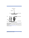
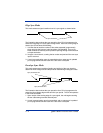
Two hardware sync inputs are available. Pin 4 is designed to be used with TTL
or open collector inputs. For open collector inputs, adding an external pull-up
resistor to 5 VDC is recommended because the internal pull-up is a relatively
high 100K ohm resistance. Pins 1 and 2 form a ground isolated input designed
to be used with systems that need separate grounds than the verifier and/or
output a higher voltage level than TTL. See the figures the follow for circuit
diagrams.


