


Monitoring and Testing
5-11
3162-A2-GB20-40
August 2000
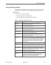
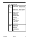
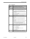
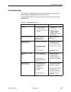
Table 5-5. IP Routing Table
Field
Description
Destination Displays the destination IP address for the route.
Mask Displays the subnet mask for the Destination IP address.
Gateway Displays the gateway IP address for the route.
Tbl Displays a code for the routing table the route resides in. Tbl is one
of:
H D – Default Table. The route is added based on the Default
Gateway Address set in the Ethernet Port Options screen, or the
Default Network Destination set in the Communication Protocol
Options screen.
H L – Local Table. The Local Table has an entry for each interface
that can have an IP address.
H R – Remote Table. This is the primary routing table, which holds
routes to other devices.
Hop Displays the number of hops in the route to the destination.
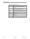
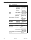
Proto Displays the protocol used to add the route to the routing table.
Proto is one of:
H RIP – The route was discovered using Routing Information
Protocol.
H Local – The route was added based the DSU/CSU’s local
configuration.
H NMS – The route was added by a Network Management System
using SNMP.
H ICMP – The route was added because an Internet Control
Management Protocol redirect message was received from a
router, indicating a better route to the destination.
H Other – None of the above methods was used. This would be
shown for a temporary route added to respond to an IP packet.
Intf Displays the interface used to reach the destination. Intf is one of:
H COM – The communications port.
H Ether – The 10BaseT port.
H FDL – The Facility Data Link.
H EDL1 – The Embedded Data Link (EDL) for Port 1.
H EDL2 – The EDL for Port 2.
H NA – Not Applicable
TTL Displays the Time To Live set for the route. 1–998 denotes a
number of seconds; 999 denotes infinity (the route never expires).