


Operating Requirements 105
Reference
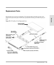
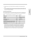
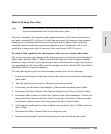
Model L10 Long-Wave Hub
Note Stated distances assume 9-micron single-mode cable for the long-wave port and
50-micron multimode cable for the short-wave ports.
For ports 1 through 9, the long-wave hub supports distances of 500 meters between the
port and a connected FC-AL device. For the long-wave port, the long-wave hub supports
distances up to 3 kilometers between two long-wave hubs. Under certain conditions,
cascaded long-wave hubs are supported at distances up to 10 kilometers. The 10-km
capability is supported only for long-wave hubs connected to HP-UX servers.
To verify 10-km capability for the long-wave hub over an existing cable plant:
The received average optical power of the long-wave port on both long-wave hubs must be
higher (more positive) than -17dBm in order for the long-wave hubs to support cascade
distances of up to 10km. Use an optical power meter that measures average optical power
at a wavelength of 1300nm in dBm units (for example, the Fotec Model 712A Power Meter
with Model A262 SC connector adapter).
To verify the long-wave port’s received average optical power, do the following:
1. Power on both long-wave hubs and connect the long-wave ports with the 10-km single-
mode cable.
2. Turn the optical power meter on. The meter performs a self-test.
3. If necessary, set the meter’s wavelength to 1300nm and measuring units to dBm.
4. Disconnect the Fibre Channel cable from the long-wave port of one of the two hubs.
5. Determine which connector of the Fibre Channel cable is the transmitter. Connect one
plug of the Fibre Channel cable into the SC receptacle of the meter. If the meter does
not indicate a signal, connect the other plug of the Fibre Channel cable.
6. Verify that the reading on the meter is higher (more positive) than -17dBm and lower
than -3dBm.
7. Reconnect the Fibre Channel cable to the long-wave port.
8. Repeat steps 4 through 7 with the long-wave port of the second long-wave hub.