


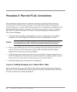
34 Procedure 5: Plan the FC-AL Connections
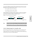
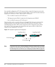
In a cascaded configuration of FC-AL long-wave hubs, connect the long-wave port on the
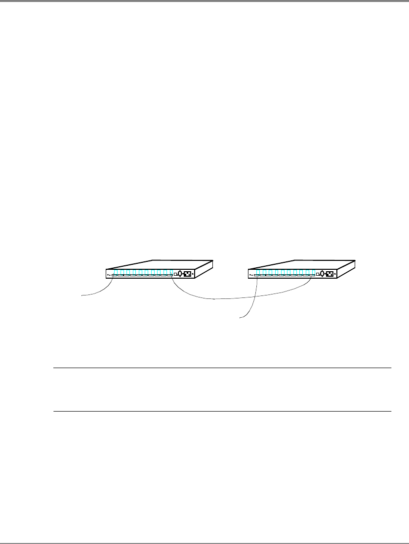
first hub to the long-wave port on the second hub. Figure14 shows all 18 nodes in the loop
formed by FC-AL Device 1, Hub A, Hub B, and FC-AL Device 2:
– Port 1 on Hub A connects to FC-AL Device 1.
– The long-wave port of Hub A connects to the long-wave port of Hub B.
– Port 1 on Hub B connects to FC-AL Device 2.
Long-wave hubs can be cascaded with ports 1 through 9 (the short-wave ports), but the
supported distance between hubs is reduced from 3000 meters to 500 meters. When
cascading long-wave hubs, ONLY connect long-wave ports to long-wave ports or short-
wave ports to short-wave ports. Any unused short-wave port on Hub A or Hub B can
connect to any compatible FC-AL device.
Figure 14 Cascaded Long-Wave Hub Configuration
Note If you plan to use Fibre Channel Manager to manage cascaded hubs, you must
configure the hub that has the LAN (ethernet) connection as a parent hub and
the remaining hub as a child hub (see Configuring Cascaded Hubs on page60).
...
...
...
...
...
...
...
...
...
...
...
...
...
...
...
...
...
...
...
...
...
...
...
...
...
...
...
...
...
...
...
...
...
...
...
...
...
...
...
...
...
...
...
...
...
...
...
...
...
...
....
.....
...
...
...
...
...
...
...
...
...
...
...
...
...
...
...
...
...
...
...
...
...
...
...
...
...
...
...
...
...
...
...
...
...
...
...
...
...
...
...
...
...
...
...
...
...
...
...
...
...
...
....
.....
FC-AL Device 1
FC-AL Device 2
Long-Wave Hub A Long-Wave Hub B