


Installing the Tape Library
L700 (CTL700) Installation and User’s Guide—527338-004
3-2
Installing the Expansion Frame
2. Using a Torx T-30 bit, remove the six mushroom attachments from the rear
of the expansion frame by turning them counterclockwise.
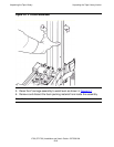
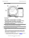
3. Position the robotic hand at the top of the Z column and facing the tape
drives.
Decals on the tape library wall show panel and column locations. Viewed
from the right rear of the tape library, locate the tape cartridge arrays at
panel 2, column 4. These arrays must be removed to allow access to the
mounting holes for the expansion frame.
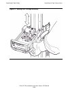
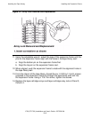
a. You might need a flashlight for this step. Refer to Figure 3-2
and insert a
flat blade screwdriver in the position shown.
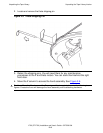
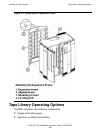
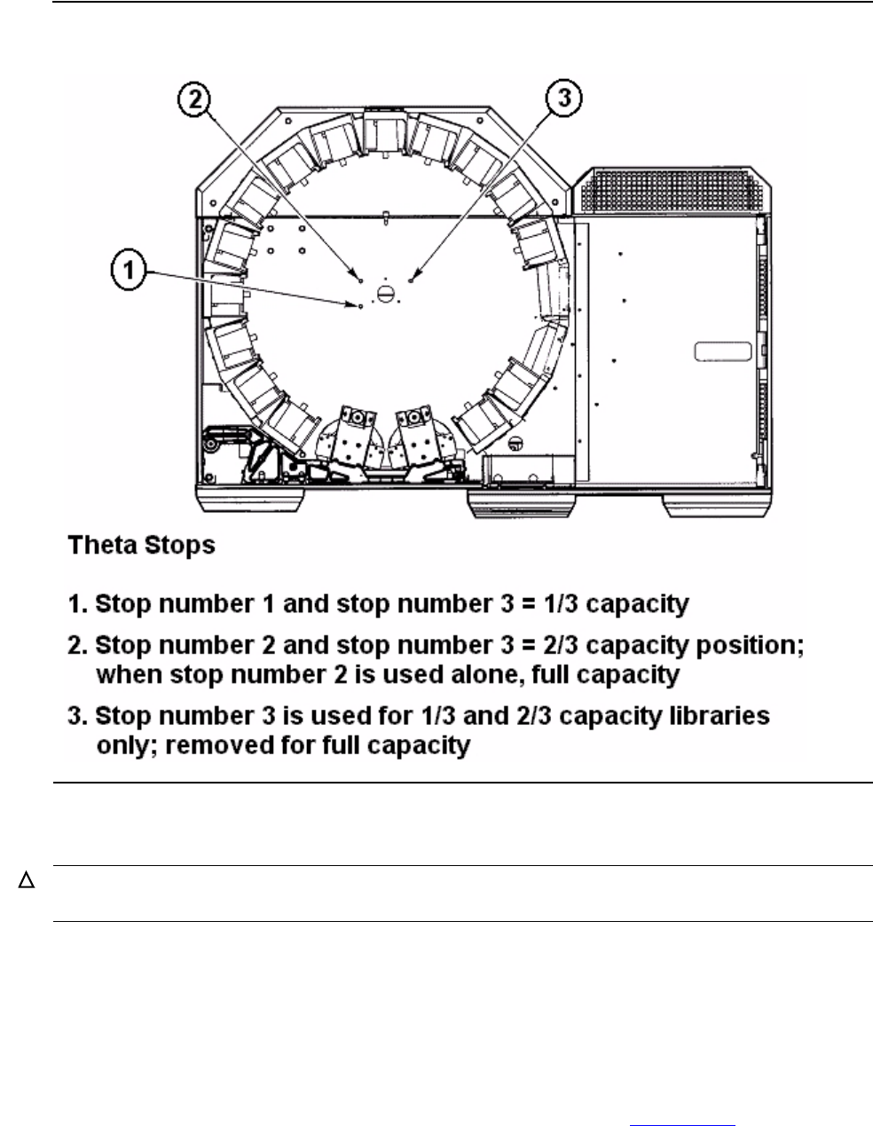
Figure 3-1. Theta Stops
Caution. Note the position of the theta lock bracket mounted on the top inside surface of the
tape library. Be careful not to hit your head on the bracket.