


Contents
L700 (CTL700) Installation and User’s Guide—527338-004
v
Safety and Compliance
Safety and Compliance
Index
Examples
Figures
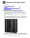
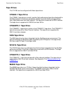
Figure 1-1. The CTL700 Tape Library 1-1
Figure 2-1. Space Needed for CTL700 Tape Library 2-2
Figure 2-2. Power and Signal Cable Routing 2-3
Figure 2-3. Unpacking the Tape Library 2-5
Figure 2-4. Column Shipping Pin 2-7
Figure 2-5. Theta Shipping Pin 2-8
Figure 2-6. Z Column Movement 2-9
Figure 2-7. Moving the Z Carriage Assembly 2-10
Figure 3-1. Theta Stops 3-2
Figure 3-2. Array Lock Removal and Replacement 3-4
Figure 3-3. Unpacking the Expansion Frame 3-5
Figure 3-4. Attaching the Expansion Frame 3-6
Figure 3-5. Tape Library Power Cable 3-11
Figure 4-1. Operator Panel Display, Control, and Indicators 4-2
Figure 4-2. Library Status Screen 4-4
Figure 4-3. FSC Log Screen 4-5
Figure 4-4. CAP Status Screen 4-5
Figure 4-5. Drive Information Menu 4-6
Figure 4-6. Cleaning Information Menu 4-7
Figure 4-7. Main Diagnostics Menu 4-8
Figure 4-8.
Version Info Menu 4-9
Figure 4-9.
Configuration Menu 4-9
Figure 4-10. Library Configuration Menu 4-10
Figure 4-11. Drive Configuration Menu 4-11
Figure 4-12. Display Information Menu 4-12
Figure 4-13. Library Power Switch Location 4-14
Figure 4-14. Tape Drive Power Switch Location 4-15
Figure 5-1. Tape Library Capacity Map - Two Tape Drive Columns 5-2
Figure 5-2. CT9840-1/CT9840FC-1/CT9841FC-1 Cartridge 5-14
Figure 5-3. Reserved Cells 5-15
Figure 5-4. Placing Tape Cartridge Into the Tape Cartridge Array Cells 5-19
Figure 5-5. Loading the CAP with a 9840 Tape Cartridge 5-20
Figure 6-1. Removing the CAP Magazine 6-5