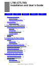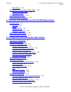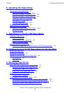
Contents
L700 (CTL700) Installation and User’s Guide—527338-004
vi
Tables
Figure 6-2. Opening the Access Doors 6-10
Figure 6-3. Extending the Gripper 6-12
Figure 6-4. Removing the Cartridge From the Hand 6-13
Figure 6-5. Loading a Cartridge Into the 9840 Tape Drive 6-14
Figure A-1. Example of the Fibre Channel Converter Configuration with a
CT9840FC-1/CT9841FC-1 Tape Drive Inside of a CTL700 Tape Library
and a NonStop Server A-2
Figure A-2. Rear Panel Components A-3
Figure A-3. Location of Fibre Channel Port on the CT9840FC-1 A-4
Figure A-4. Location of the GBIC on the CT9800FC Fibre Channel Converter A-4
Figure A-5. FC LED Not Illuminated A-5
Figure A-6. FC LED Illuminated A-6
Figure A-7. Example of the CT9800FC Fibre Channel Converter Configuration With
a CTL700 Tape Library and a Nonstop Server A-7
Figure A-8. Rear Panel Components A-8
Figure A-9. Location of the CTL7FC Fibre Channel Interface Card Inside the
CTL700 Tape Library A-9
Figure A-10. Location of the GBIC on the CT9800FC Fibre Channel
Converter. A-10
Figure A-11. FC LED Not Illuminated A-11
Figure A-12. FC LED Illuminated A-11
Figure D-1. Fibre Channel Router Rear View D-2
Figure D-2. Fibre Channel Router Rear View D-3
Figure D-3. View of Column 1 D-4
Figure D-4. Main Menu D-5
Figure D-5. Drive Info D-6
Figure D-6. Drive Information D-7
Figure D-7.
WWN Drive Info D-8
Tables
Table 3-1. Terminate the SCSI BUS 3-12
Table 5-1. Tape Library Configuration Selection 5-3
Table 5-2. Tape Drive Configuration Form 5-4
Table 6-1. Tape Drive Status Messages 6-2
Table 6-2. CAP Status Messages 6-3
Table 6-3. Tape Drive Diagnostic Tests 6-8
Table 9-1. Methods for Controlling Data Compression 9-13
Table A-1. Connections Supported for the CT9800FC Fibre Channel
Converter A-3
Table A-2. Connections Supported for the CT9800FC Fibre Channel
Converter A-8


