


Getting started
Deploying the M111
2-2
Deploying the M111
This chapter provides step-by-step instructions that explain how to configure the M111 for
the following frequently used deployments.
Scenario 1: Connecting wired devices to a wireless network on page 2-2
Scenario 2: Connecting a wired device using MAC address cloning on page 2-8
Scenario 3: Connecting a serial device to a wireless network on page 2-11
Scenario 1: Connecting wired devices to a
wireless network
This scenario explains how to use the M111 to connect several wired devices to a network via
a wireless link.
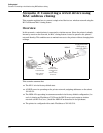
Overview
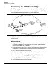
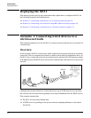
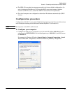
In this scenario, the M111 connects two wired computers to a private network via a wireless
connection. The two computers are linked to a hub or switch which is plugged into Port 1 on
the M111. Once connected to the private network via the wireless link, the computers obtain
an IP address from the DHCP server and can then communicate with resources on the private
network.
(Although this scenario shows two connected devices, up to 20 Ethernet devices can share
the wireless link, with each device getting its own unique IP address from the DHCP server.)
This scenario assumes that:
The M111 is in its factory-default state.
A DHCP server is operating on the private network, assigning addresses on the subnet
192.168.5.0.
Private network with
DHCP server on
subnet 192.168.5.0
MSM AP
R
e
s
e
t
Switch/Hub
5.11
Port 1
5.26
5.27
5.11
5.25
5.25