


Chapter 1 13
Introduction
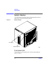
System displays
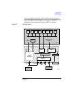
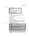
Figure 4 Front panel LCD
When the node key switch is turned on, the LCD powers up but is
initially blank.
Power-On Self Test (POST) starts displaying output to the LCD. The
following illustrates this output shown in Figure 4:
Node status line
The Node Status Line shows the node ID in both decimal and X, Y
topology formats.
Processor status line
The processor status line shows the current run state for each processor
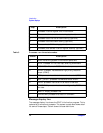
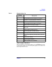
in the node. Table 2 shows the initialization step code definitions and
Table 3 shows the run-time status codes. The M in the first processor
status line stands for the monarch processor.
Table 2 Processor initialization steps
MIII IIII IIII IIII
0 (0,0)
IIII IIII IIII IIII
abcedfghijklr
Step Description
0 Processor internal diagnostic register initialization
1 Processor early data cache initialization.
2 Processor stack SRAM test.(optional)
3 Processor stack SRAM initialization.
4 Processor BIST-based instruction cache initialization.
5 Processor BIST-based data cache initialization