


HP Omnibook XT6050, XT/VT6200 Product Information 1-15
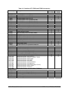
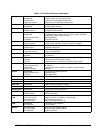
Table 1-9. Functional Structure Description
Bootup
CPU module
Motherboard
Hard disk drive
Floppy disk module
Main processor (MMO).
Primary system circuitry, system BIOS.
First source of disk-based startup code.
Second source of disk-based startup code.
Processor
CPU module
Motherboard
Main processor, numeric data processor, L1 and L2 cache.
Primary system circuitry.
Memory
Motherboard
SDRAM module
Video RAM, no onboard RAM.
Changeable RAM (2 slots).
Power
Battery
Motherboard
Display interface PCA.
AC adapter
Power storage.
AC adapter socket, power switch, lid switch, system-off switch,
power supply, power control circuitry.
Blue sleep button.
AC-to-DC converter.
Display
Motherboard
Display assembly
Graphics controller, video RAM.
Display output, backlight, power converter for backlight.
Hard disk
Motherboard
Hard disk drive
Hard disk controller.
Hard disk mechanism.
Floppy drive
Motherboard
Floppy disk module
I/O controller, floppy connector.
Floppy disk mechanism.
Keyboard
Motherboard
Keyboard
Keyboard BIOS, keyboard controller.
Key switches.
Pointer
Motherboard
Keyboard
Top case
Keyboard circuitry, keyboard controller, keyboard BIOS.
Pointing stick sensor (certain models).
Touch pad sensor, click buttons, controller (PS/2 output).
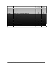
Audio
Motherboard
Display interface PCA
Volume PCA
Speaker assembly
Audio controller, audio decoder, speaker amplifier.
Microphone.
External audio jacks, headphone amplifier, audio-off switch.
Speakers.
Status
Motherboard
Display interface PCA
Top case
LED circuitry, keyboard controller.
Keyboard LEDs.
Main status LEDs.
Serial
Motherboard I/O controller, serial connector.
Parallel
Motherboard I/O controller, parallel connector.
Infrared
Motherboard I/O controller, infrared transmitter/receiver.
PS/2 port
Motherboard PS/2 connector, keyboard controller.
USB
Motherboard Bus controller (South Bridge), USB connector.
Docking port
Motherboard Docking logic, docking connector.
PCMCIA
Motherboard
PCMCIA socket
PCMCIA controller.
PCMCIA connector.
Wireless
LAN
Motherboard
Front antenna PCA
Rear antenna PCA
Mini-PCI card #1
I/O controller.
Receive antenna, on-off button, indicator light.
Transmit/receive antenna.
Radio, radio frequency circuitry.
LAN
Motherboard
Mini-PCI panel
LAN circuitry, bus controller.
LAN connector.
Modem
Mini-PCI card #1
Mini-PCI card #2
Mini-PCI panel
Modem circuitry (certain models).
Modem circuitry (certain models).
Modem connector.