


2-32 Removal and Replacement HP Omnibook XT6050, XT/VT6200
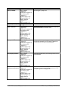
Component Removal Procedure Additional Steps
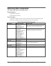
Doors, PCMCIA
Plug-in module
(page 2-5).
Hard disk drive (page 2-7).
Power button panel
(page 2-11).
Keyboard (page 2-13).
Heatsink (page 2-15).
Display assembly
(page 2-19).
Top case (page 2-21).
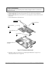
See the figure on page 2-25.
Heatsink (with fan)
See page 2-15.
Keyboard
See page 2-13.
Panel, sound/IR
Plug-in module
(page 2-5).
Hard disk drive (page 2-7).
Power button panel
(page 2-11).
Keyboard (page 2-13).
Heatsink (page 2-15).
Display assembly
(page 2-19).
Top case (page 2-21).
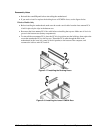
Reassembly Notes:
Insert the tabs on the ends of the
panel into the slots in the bottom case.
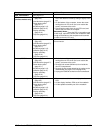
Panel, mini-PCI
Plug-in module
(page 2-5).
Hard disk drive (page 2-7).
Power button panel
(page 2-11).
Keyboard (page 2-13).
Heatsink (page 2-15).
Display assembly
(page 2-19).
Top case (page 2-21).
On the rear of the computer, remove the screw at the
far left end (nearest the mini-PCI panel).
Detach the
cables from mini-PCI card and motherboard.
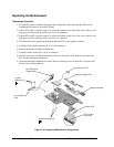
PCA, display interface
Plug-in module
(page 2-5).
Hard disk drive (page 2-7).
Power button panel
(page 2-11).
Keyboard (page 2-13).
Heatsink (page 2-15).
Display assembly
(page 2-19).
Top case (page 2-21).
Unplug the speaker cable, and carefully lift the PCA off
of its connector.
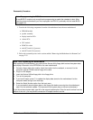
PCA, front antenna
(wireless models only)
Plug-in module
(page 2-5).
Hard disk drive (page 2-7).
Power button panel
(page 2-11).
Keyboard (page 2-13).
Heatsink (page 2-15).
Display assembly
(page 2-19).
Top case (page 2-21).
Disconnect the front antenna PCA flex cable from the
motherboard, and the coaxial cable from the mini-PCI
card (see Figure 2-19 on page 2-26).