


HP Omnibook XT6050, XT/VT6200 Removal and Replacement 2-31
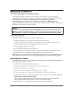
Removing Other Components
(HP Authorized Service Providers Only)
Required Equipment
•
Small Phillips screwdriver.
•
Small flat-blade screwdriver.
Removal Procedure
1.
Unplug the AC adapter, if present, and remove the battery and any secondary battery module.
2.
Remove the assemblies and follow the additional steps given in the table below.
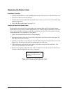
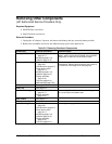
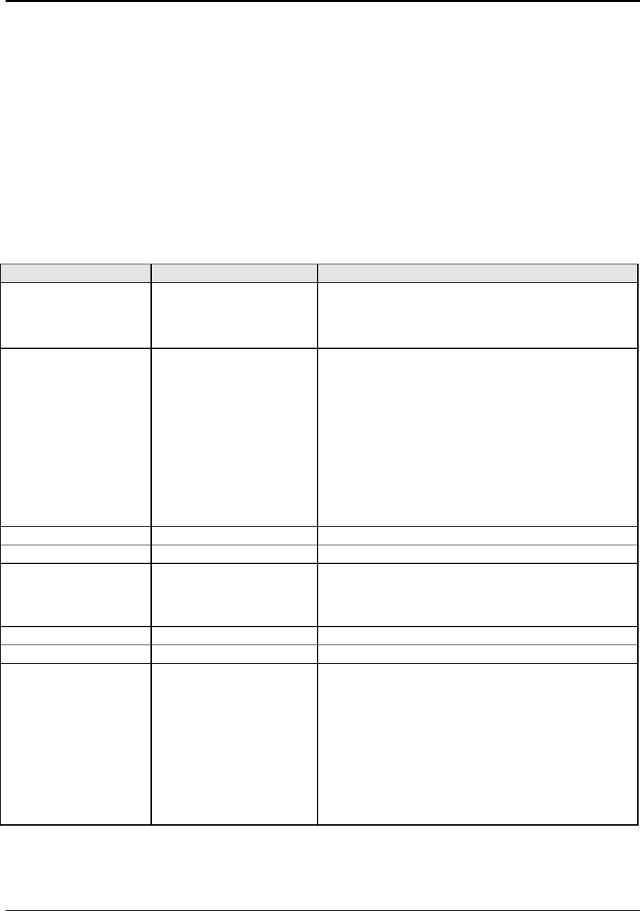
Table 2-5. Removing Omnibook Components
Component Removal Procedure Additional Steps
Battery, CMOS
Power button panel
(page 2-11).
Keyboard (page 2-13).
Heatsink (page 2-15).
Reassembly Notes:
After replacing the CMOS
battery, set the correct time and date using the BIOS
Setup utility or Date/Time in the Control Panel.
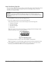
Card, mini-PCI #2
Plug-in module
(page 2-5).
Hard disk drive (page 2-7).
Power button panel
(page 2-11).
Keyboard (page 2-13).
Heatsink (page 2-15).
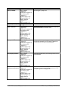
Display assembly
(page 2-19).
Top case (page 2-21).
Motherboard (page 2-23).
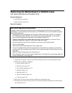
The card is attached to the underside of the
motherboard. Release the two latches at the sides of
the card so the free edge of the card pops up.
Case, bottom
See page 2-23.
Case, top
See page 2-21.
Cover, center hinge
Power button panel
(page 2-11).
Display assembly
(page 2-19).
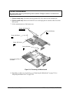
Reassembly Note:
Make sure the center hinge cover
fits over the tab in the bottom case.
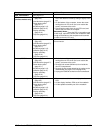
CPU module
See page 2-17.
Display assembly
See page 2-19.
Doors, docking
Plug-in module
(page 2-5).
Hard disk drive (page 2-7).
Power button panel
(page 2-11).
Keyboard (page 2-13).
Heatsink (page 2-15).
Display assembly
(page 2-19).
Top case (page 2-21).
See the figure on page 2-25.