


HP Omnibook XT6050, XT/VT6200 Removal and Replacement 2-1
2
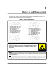
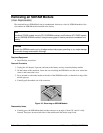
Removal and Replacement
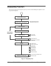
This chapter tells you how to remove and replace the Omnibook’s components and assemblies. The
items marked by
•
in the following table are user-replaceable.
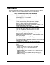
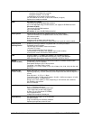
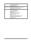
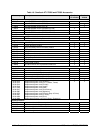
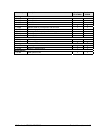
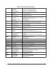
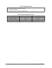
Table 2-1. Removal Cross-Reference
•
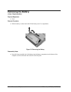
Battery, main (page 2-4).
Battery, CMOS (page 2-31).
•
Bumpers, display (page 2-12)
•
Cap, pointing stick (page 2-12).
•
Card, mini-PCI #1 (page 2-10).
Card, mini-PCI #2 (page 2-31).
Case, bottom (page 2-23).
Case, top (page 2-21).
Cover, center hinge (page 2-31).
•
Cover, left corner (page 2-12).
•
Cover, mini-PCI (page 2-12).
•
Cover, SDRAM (page 2-12).
•
Cover, right corner (page 2-12).
•
Covers, screw (page 2-12).
CPU module (page 2-17).
Display assembly (page 2-19).
Doors, docking (page 2-25).
Doors, PCMCIA (page 2-25).
•
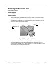
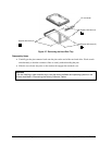
Drive, hard disk (page 2-7).
•
Feet, rubber (page 2-12).
Heatsink (with fan) (page 2-15).
Keyboard (page 2-13).
Panel, sound/IR (page 2-32).
Panel, mini-PCI (page 2-32).
•
Panel, power button (page 2-11).
PCA, display interface (page 2-32).
PCA, motherboard (page 2-23).
PCA, volume (page 2-33).
PCA, front antenna (page 2-32).
PCA, rear antenna (page 2-33).
•
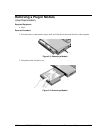
Plug-in module (page 2-5).
•
SDRAM module (page 2-6).
Socket, PCMCIA (page 2-33).
Speaker assembly (page 2-33).
•
Tray, hard disk drive (page 2-7).
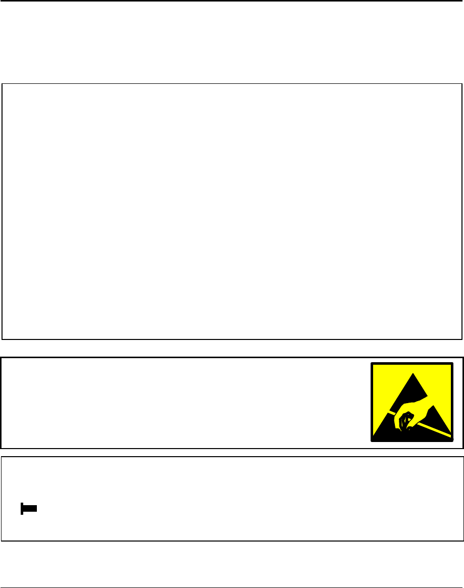
Caution
Always provide proper grounding when performing repairs. Without proper
grounding, an electrostatic discharge can damage the Omnibook and its
components.
Notes
Reassembly steps are the reverse of the removal steps. Reassembly notes are included at the end
of each section below.
Symbols like this throughout this chapter show approximate full-size screw outlines. You can
use these to verify the sizes of screws before you install them. Installing a wrong-size screw can
damage the unit. (The symbol at the left represents an M2.5×5mm T-head screw.)