


2-26 Removal and Replacement HP Omnibook XT6050, XT/VT6200
Replacing the Motherboard
Disassembly Procedure
1.
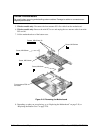
If a mini-PCI panel is attached, disconnect the LAN/modem cables from the mini-PCI card or
motherboard and remove the mini-PCI panel.
2.
If mini-PCI card #1 is present, remove it: release the latches at the sides of the card, so that its free
edge pops up, then carefully pull the card out of its connector.
3.
If mini-PCI card #2 is present, remove it: release the latches at the sides of the card, so that its free
edge pops up, then carefully pull the card out of its connector.
4.
Disconnect the cable connecting the display interface PCA to the speaker assembly.
5.
Carefully lift the display interface PCA off of its connector.
6.
Remove the speaker assembly from the unit.
7.
Carefully lift the volume PCA off of its connector.
8.
Turn the lock screw one-half turn counterclockwise to release the CPU module, and remove the
CPU module from the motherboard.
9.
From underneath the motherboard, remove the two retaining screws from the PC card socket and
lift the socket off the connector.
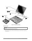
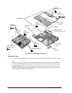
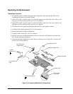
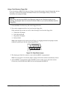
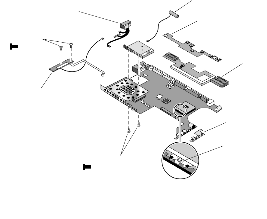
Figure 2-19. Replacing Motherboard Components
Volume PCA
CPU module
lock screw
Display interface PCA
Screws, M2x4mm (2)
Speaker assembly
Mini-PCA panel
(LAN/modem)
Front antenna
PCA
Rear antenna PCA
Screws,
M2x4mm (2)