


Technology Code ID) Removal and Replacement 2-1
2
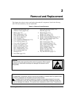
Removal and Replacement
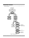
This chapter shows how to remove and replace the notebook’s components, listed in the following
table. The items marked by
• are user-replaceable.
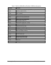
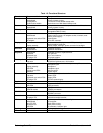
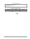
Table 2-1. Removal Cross-Reference
Antenna, Bluetooth (page 2-20).
Antenna, wireless (page 2-20).
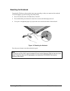
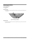
• Battery (page 2-4).
Bezel, display (page 2-20).
Card, mini-PCI (page 2-16).
Case, bottom (page 2-32).
Case, top (page 2-27).
• Cover, expansion SDRAM (page 2-15).
• Cover, keyboard (page 2-9).
• Cover, mini-PCI (page 2-15).
• Covers, screw (page 2-15).
Display assembly (page 2-18).
Doors, docking (page 2-35).
Doors, PCMCIA (page 2-35).
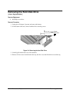
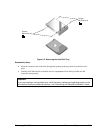
• Drive, hard disk (page 2-6).
Fan (page 2-22).
• Feet, rubber (page 2-15).
Guide, hard disk drive (page 2-38).
Heatsink (page 2-22).
• Keyboard (page 2-11).
Module, CPU (page 2-25).
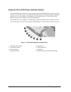
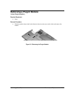
• Module, plug-in (page 2-5).
• Module, expansion SDRAM (page 2-13).
• Module, system SDRAM (page 2-14).
PCA, audio (page 2-37)
PCA, inverter (page 2-20)
PCA, motherboard (page 2-32).
PCA, volume control (page 2-39).
Saddles, hinge (page 2-30).
Socket, PCMCIA (page 2-39).
Speaker, left (page 2-39).
Speaker, right (page 2-39).
• Tray, hard disk drive (page 2-7).
Caution
Always provide proper grounding when performing repairs. Without proper
grounding, an electrostatic discharge can damage the notebook and its
components.
Notes
To reassemble a component, perform the removal procedure in reverse order. Any special notes
required for reassembly are included at the end of each section.
Symbols like this are used throughout this chapter to show approximate full-size screw
outlines. Use these to verify the sizes of screws before you install them. Installing a wrong-size
screw can damage the notebook. (The symbol shown represents an M2.5×5mm T-head screw.)