


iv Technology Code ID)
Replaceable Parts ...........................................................................................................4-1
Reference Information...................................................................................................5-1
Password Removal Policy.............................................................................................................5-1
Hewlett-Packard Display Quality Statement.................................................................................5-2
Figures
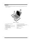
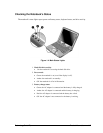
Figure 1-1. Front View.........................................................................................................................1-3
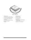
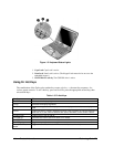
Figure 1-2. Back View.........................................................................................................................1-4
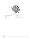
Figure 1-3. Bottom View .....................................................................................................................1-5
Figure 1-4. Main Status Lights.............................................................................................................1-7
Figure 1-5. Keyboard Status Lights .....................................................................................................1-8
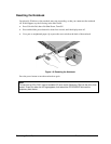
Figure 1-6. Resetting the Notebook.....................................................................................................1-9
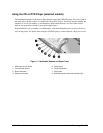
Figure 1-7. Multimedia Buttons and Status Panel..............................................................................1-10
Figure 1-8. Replaceable Module Diagram.........................................................................................1-14
Figure 2-1. Disassembly Flow..............................................................................................................2-2
Figure 2-2. Removing the Battery........................................................................................................2-4
Figure 2-3. Releasing the Plug-in Module...........................................................................................2-5
Figure 2-4. Removing the Hard Disk Drive.........................................................................................2-6
Figure 2-5. Removing the Hard Disk Tray ..........................................................................................2-7
Figure 2-6. Removing the Keyboard Cover Retaining Screws............................................................2-9
Figure 2-7. Removing the Keyboard Cover.......................................................................................2-10
Figure 2-8. Loosening the Keyboard Retaining Screws.....................................................................2-11
Figure 2-9. Disconnecting the Keyboard ...........................................................................................2-12
Figure 2-10. Removing an Expansion SDRAM Module...................................................................2-13
Figure 2-11. Installing an Expansion SDRAM Module.....................................................................2-14
Figure 2-12. Removing the System SDRAM Module.......................................................................2-14
Figure 2-13. Removing the Mini-PCI Card .......................................................................................2-17
Figure 2-14. Removing the Display (1) .............................................................................................2-18
Figure 2-15. Removing the Display (2) .............................................................................................2-19
Figure 2-16. Removing Display Assembly Components...................................................................2-21
Figure 2-17. Removing the Fan and Heatsink....................................................................................2-23
Figure 2-18. Installing a New Thermal Pad.......................................................................................2-24
Figure 2-19. Removing the CPU Module ..........................................................................................2-26
Figure 2-20. Removing the Top Case Retaining Screws ...................................................................2-27
Figure 2-21. Removing the Top Case ................................................................................................2-29
Figure 2-22. Removing the Hinge Saddles ........................................................................................2-31
Figure 2-23. Removing the Motherboard...........................................................................................2-33
Figure 2-24. Installing the Docking Doors ........................................................................................2-35
Figure 2-25. Installing the PCMCIA Doors.......................................................................................2-35
Figure 2-26. Example of Serial Number Label..................................................................................2-36
Figure 3-1. Basic Troubleshooting Steps.............................................................................................3-2
Figure 3-2. e-Diagtools Screens — Basic and Advanced..................................................................3-22
Figure 3-3. Parallel Loopback Connector..........................................................................................3-24
Figure 4-1. Exploded View..................................................................................................................4-2