


5.10.6.2 Boot loader
After the system completes the hardware diagnostics setup in the firmware, the first program that runs is the
boot loader. The boot loader is responsible for copying the boot image from hard disk and then transferring
control to it. SLES supports GRUB, which lets you set pointers in the boot sector to the kernel image and to
the RAM file system image.
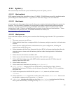
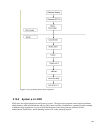
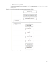
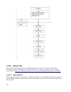
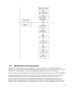
5.10.6.3 Boot process
The boot process consists of the following steps when the CPU is powered on or reset:
1. BIOS probes hardware, establishes which devices are present, and runs Power-On Self Test (POST).
BIOS, is not part of TOE.
2. BIOS initializes hardware devices and makes sure they operate without IRQ or I/O port conflicts.
3. BIOS searches for the operating system to boot in an order predefined by the BIOS setting. Once a
valid device is found, BIOS copies the contents of its first sector containing the boot loader into RAM
and starts executing the code just copied.
4. The boot loader is invoked by BIOS to load the kernel and the initial RAM file system into the
system’s RAM. It then jumps to the setup() code.
5. The setup() function reinitializes the hardware devices in the computer and sets the environment
for the execution of the kernel program. The setup() function initializes and configures hardware
devices, such as the keyboard, video card, disk controller, and floating point unit.
6. The boot loader reprograms the Programmable Interrupt Controller and maps the 16 hardware
interrupts to the range of vectors from 32 to 47. The boot loader switches the CPU from Real Mode
to Protected Mode and then jumps to the startup_32() function.
7. The boot loader initializes the segmentation registers and provisional stack. It fills the area of
uninitialized data of the kernel with zeros.
8. The boot loader decompresses the kernel, moves it into its final position at 0x00100000, and jumps to
that address.
9. The boot loader calls the second startup_32() function to set the execution environment for
process 0.
10. The boot loader prepares to enable long mode by enabling Physical Address Extensions and Page
Global Enable.
11. The boot loader sets early boot stage 4 level page tables, enables paging, and Opteron long mode. It
jumps to reach_compatibility_mode(), loads GDT with 64-bit segment and starts operating
in 64-bit mode.
12. Initializes the segmentation registers.
13. Sets up the kernel mode stack for process 0.
14. Fills the bss segment of the kernel with zeros.
15. Sets up the IDT with null interrupt handlers. Puts the system parameters obtained from the BIOS and
the parameters passed to the operating system into the first page frame.
16. Identifies the model of the processor. Loads gdtr and idtr registers with the addresses of the
Global Descriptor Table (GDT) and Interrupt Descriptor Table (IDT) and jumps to the
x86_64_start_kernel() function.
169