


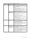

Table 4. Descriptions of light-path diagnostics LEDs
LED Meaning
PS1 Power supply 1 failure
PS2 Power supply 2 failure
PS3 Power supply 3 failure
NON Non-redundant power
OVER The system has exceeded the power capabilities of the installed power supplies
NMI Non-maskable-interrupt occurred
TEMP System temperature exceeded maximum rating
FAN A fan failed or is operating slowly
MEM Memory failure. One or more memory DIMMs have failed
CPU Microprocessor failure. One or both microprocessors have failed
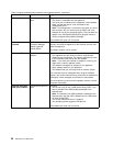
PCI A Error on PCI channel A or system board. Note: PCI bus A is often referred to as PCI bus 0
PCI B Error on PCI channel B or system board. Note: PCI bus B is often referred to as PCI bus 1
PCI C Error on PCI channel C or system board. Note: PCI bus C is often referred to as PCI bus 2
VRM VRM Error on voltage regulator module or on integrated voltage regulator
DASD A hot-swap disk drive, backplane, or other part of SCSI channel A has failed
SP Integrated System Management Processor detected an error
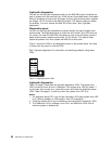
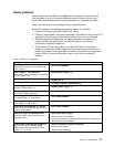
Remind button: You can use the remind button to place the front panel
system-error light into a remind mode. By pressing the button, you acknowledge the
failure but indicate that you will not take immediate action. If a new error occurs, the
LED will be on again.
In the remind mode, the system-error LED flashes every 2 seconds. The
system-error LED remains in remind mode until one of the following situations
occurs:
1. All known problems are resolved
2. The system is restarted
3. A new problem occurs
You can use the remind button to delay maintenance. Also, resetting the
system-error LED enables the LED to react to another error. If the LED is still
blinking from the first error, it will mask additional errors.
Chapter 7. Troubleshooting 51