


98 IBM® xSeries 220 User’s Reference
12. Turn off the server.
13. Move jumper J38 to the "hi" setting (pins 1 and 2) to return to normal startup
mode.
14. Restart the server.
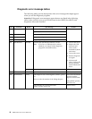
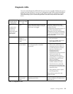
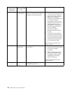
Identifying problems using status LEDs
Your server has LEDs to help you identify problems with some server components.
These LEDs are part of the diagnostics that are built into the server. Use the
illuminated LEDs to identify the failing or incorrectly installed components.
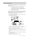
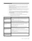
Front panel and system board LEDs
The system error LED is on the front panel inside the server. All of the remaining error
LEDs are on the system board, adjacent to the failing components. See “Diagnostic
LEDs” on page 99 for information on identifying problems using these LEDs.
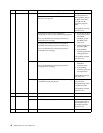
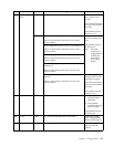
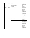
The meanings of these LEDs are as follows:
CPU 1 Microprocessor number 1 (connector U12) fault
CPU 2 Microprocessor number 2 (connector U11) fault
Fan 1 Fan number 1 (connector J10) failure (see note 1)
Fan 2 Fan number 2 (connector J18) failure (see note 1)
Fan 3 Fan number 3 (connector J22) failure (see note 1)
DIMM 1 DIMM number 1 (connector DIMM 1) fault
DIMM 2 DIMM number 2 (connector DIMM 2) fault
DIMM 3 DIMM number 3 (connector DIMM 3) fault
DIMM 4 DIMM number 4 (connector DIMM 4) fault
VRM 1 Microprocessor VRM number 1 (connector J42) fault
(see note 1)
VRM 2 Microprocessor VRM number 2 (connector J12) fault
(see note 1)
Notes:
1. The fan and VRM LEDs will illuminate only if the optional system-management
adapter is installed in the server.
2. The server does not support user-replaceable power supplies or fans.