


30 IBM® xSeries 220 User’s Reference
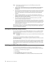
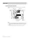
System-board jumpers and switches
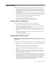
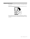
The following illustration identifies the jumpers and switches on the system board.
System-board jumper blocks
Any jumper blocks on the system board that are not shown in the illustration are
reserved. For normal operation of the system, no jumpers should be installed on any
of the jumper blocks. See “Recovering the BIOS code” on page 97 for information
about the flash ROM page-swap jumper.
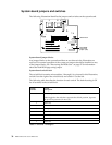
System-board switch block
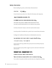
The switch block contains microswitches 1 through 8. As pictured in this illustration,
switch 8 is at the right of the switch block, and switch 1 is at the left.
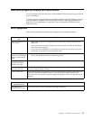
The following table describes the function for each switch. The default setting is Off
for all switches in the switch block.
Switch
number
Switch
description
8 Power-on password-override switch.
When toggled to the side that is opposite the default position, bypasses
the power-on password, if one is set.
7 Reserved.
6 Reserved.
5 Force power on.
4 Reserved.
3 Reserved.
2 Reserved.
1 Reserved.
Table 3. Switches 1 through 8
Flash ROM
page-swap
jumper (J38)
Switch block