


Chapter 5. Installing options 39
Removing the support bracket assembly
When working with some options such as hard disk drives and microprocessors, you
must first remove the support bracket assembly to access the location of the option.
The support bracket assembly consists of a support bracket, an air baffle, and a fan.
To remove the support bracket assembly, do the following:
1. Review the safety precautions in “Safety information” on page 32.
2. Turn off the server and peripheral devices and disconnect all external cables and
power cords.
3. Remove the side cover (see “Removing the side cover” on page 38 for details).
4. If your server is a non-hot-swap model, continue with step 6.
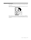
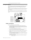
5. If your server is a hot-swap model, press down on the latches on either side of
connector J42, and remove the voltage regulator module (VRM) from connector
J42. (See “System-board option connectors” on page 28 for connector locations.)
Note: Remember to reinstall this VRM after you reinstall the support bracket
assembly.
6. Disconnect the fan cable (connector J10) from the system board. (See “System-
board internal cable connectors” on page 29 for connector locations.)
Note: Remember to reconnect this cable after you reinstall the support bracket
assembly.
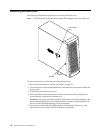
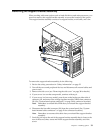
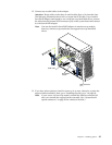
7. Carefully pull up on the end of the support bracket assembly that is closer to the
rear of the server; then, rotate and lift the support bracket assembly out of the
server.