


50 IBM® xSeries 220 User’s Reference
Note: The hard disk drive activity light and hard disk drive status light on the
backplane match the hard disk drive activity light and hard disk drive status
light on the hot-swap drive.
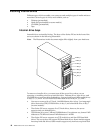
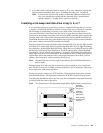
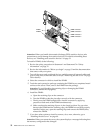
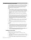
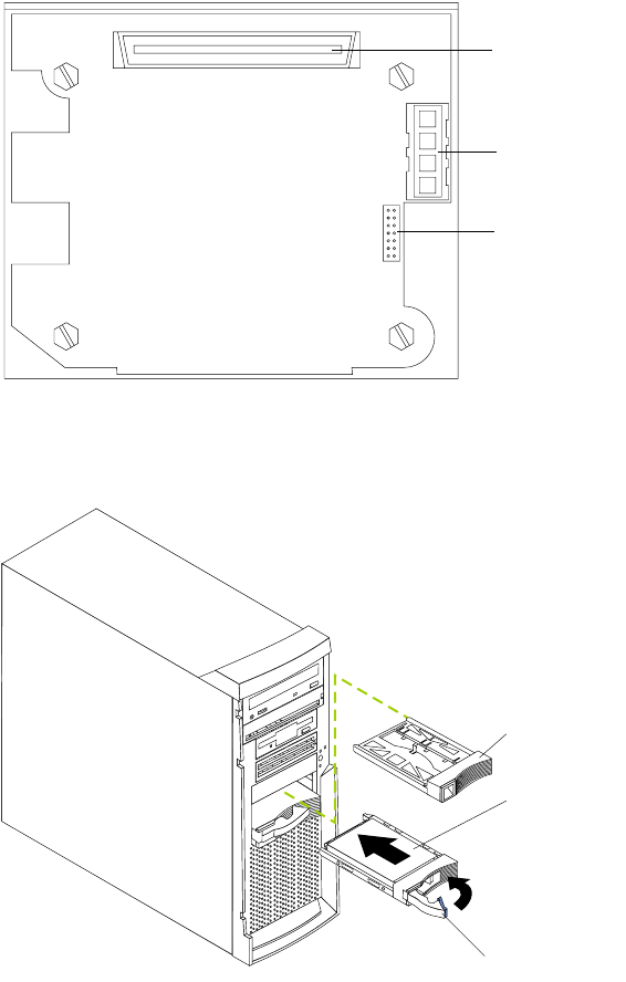
The following illustration shows the rear connectors on the hot-swap-drive
backplane, as viewed from the rear of the server.
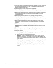
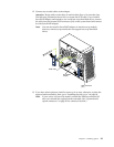
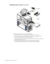
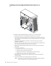
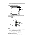
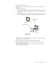
The following illustration shows how to install a hot-swap hard disk drive in the
server. When you install hot-swap hard disk drives, install them in the following
order: bay 7, bay 6, and bay 5.
Attention:
• When you handle electrostatic discharge (ESD) sensitive devices, take
precautions to avoid damage from static electricity. For details on handling these
devices, see “Handling static-sensitive devices” on page 31.
• To maintain proper system cooling, do not operate the server for more than 10
minutes without either a drive or a filler panel installed in each bay.
To install a hot-swap hard disk drive in bay 5, 6, or 7, do the following:
1. Review “Before you begin” on page 31.
2. Read the information in “Preinstallation steps (all bays)” on page 45.
SCSI cable
connector
SCSI power
cable connector
I C cable
connector
2
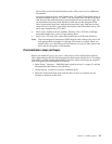
Filler panel
Drive tray
assembly
Drive tray handle
(in open position)