


v When you restart the server after you add or remove a DIMM, the server
displays a message that the memory configuration has changed.
v Memory cards in connectors 1 and 2 support microprocessor 1, memory cards in
connectors 3 and 4 support microprocessor 2, memory cards in connectors 5 and
6 support microprocessor 3, and memory cards in connectors 7 and 8 support
microprocessor 4.
v There are four memory power buses, which are split among the eight memory
cards.
v Populate the memory-card connectors to match the microprocessor installation,
in the following order: 1, 7, 3, 5, 2, 8, 4, 6. (Microprocessors must be installed in
the following order: 1, 4, 2, and 3. See “Installing a microprocessor” on page 73
for more information.)
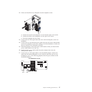
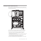
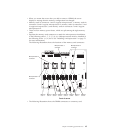
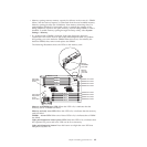
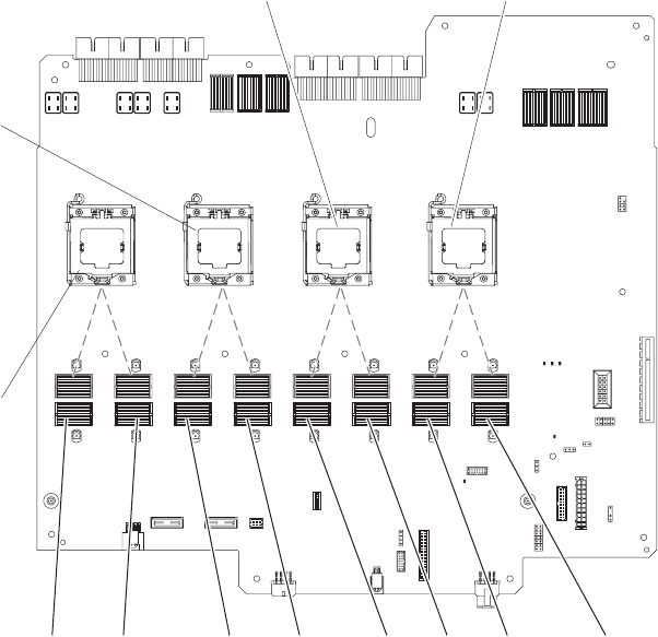
The following illustration shows the locations of the memory-card connectors.
Memory
card 1
Memory
card 2
Memory
card 3
Memory
card 4
Memory
card 5
Memory
card 6
Memory
card 7
Memory
card 8
Microprocessor 1
connector
Microprocessor 2
connector
Microprocessor 3
connector
Microprocessor 4
connector
Front of server
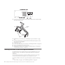
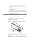
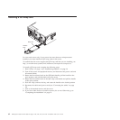
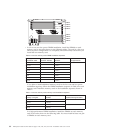
v The following illustration shows the DIMM connectors on a memory card.
Chapter 2. Installing optional devices 65