


v Double-device data correction support is only available when 16 GB x4 DRAM
technology DIMMs are installed in the memory expansion module and the
memory expansion module is connected to a host server.
v The memory expansion module supports memory sparing through the host
server. Memory sparing reserves memory capacity for failover in the event of a
DIMM failure, and the reserved capacity is subtracted from the total available
memory. Memory sparing provides less redundancy than memory mirroring
does. If a predetermined threshold of correctable errors is reached, the contents
of the failing DIMM are copied to the spare memory, and the failing DIMM or
rank is disabled. To enable memory sparing through the Setup utility, select
System Settings > Memory.
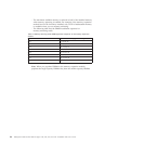
v When you populate DIMMs in the memory expansion module, populate the
larger capacity DIMMs first; then the smaller capacity DIMMs. See Table 12 on
page 85 for non-mirroring mode DIMM population sequence and Table 13 on
page 86 for memory-mirroring mode DIMM population sequence.
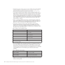
v The memory expansion module provides eight memory ports (memory
channels) and each memory port supports up to four DIMMs. Do not mix
DIMMs with x4 technology (DIMMs with DRAMs that are organized with 4
data lanes) and x8 technology (DIMMs with DRAMs that are organized with 8
data lanes) in the same memory port.
Table 10. Memory ports and DIMM connectors
Memory ports DIMM connectors
1 1,2,7,and8
2 3,4,5,and6
3 9, 10, 15, and 16
4 11, 12, 13, and 14
5 17, 18, 23, and 24
6 19, 20, 21, and 22
7 25, 26, 31, and 32
8 27, 28, 29, and 30
Note: 2 GB, 4 GB, and 8 GB DIMMs are x4 technology DIMMs. 16 GB and 32 GB DIMMs
are x8 technology DIMMs.
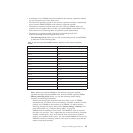
v Do not mix DIMMs with 1 Gb (gigabit) technology, 2 Gb DRAM technology, or
other gigabit DRAM technologies in banks of eight DIMMs on memory ports
that are on the same memory controller. This is not supported in the memory
expansion module. The following table lists the DIMM connectors for each bank
of eight DIMMs that are on the memory ports within the same memory
controller.
Table 11. DIMM banks and connectors
Bank of DIMMs DIMM connectors
1st bank of DIMMs 1, 2, 3, 4, 5, 6, 7, and 8
2nd bank of DIMMs 9, 10, 11, 12, 13, 14, 15, and 16
3rd bank of DIMMs 17, 18, 19, 20, 21, 22, 23, and 24
4th bank of DIMMs 25, 26, 27, 28, 29, 30, 31, and 32
v DIMMs must be installed in pairs for non-mirroring mode and in sets of four for
memory-mirroring mode.
84 IBM System x3850 X5 and x3950 X5 Types 7145, 7146, 7143, and 7191: Installation and User's Guide